Improved row cleaner and row closer assemblies for strip till planters

a technology of cleaner and planter, which is applied in the field of improved row cleaning and row closing in strip till farming applications, can solve the problems of row cleaner's weight and zero-angle position not being able to adequately perform row clearing operation, row cleaner may double back on itself, and too aggressively engage the soil

Pending Publication Date: 2022-07-07
MARTIN RONALD STEVE
View PDF13 Cites 1 Cited by
  • Summary
  • Abstract
  • Description
  • Claims
  • Application Information

AI Technical Summary

Benefits of technology

[0014]The present invention provides a row cleaner system that provides an effective and efficient solution that improves both row cleaning operation in strip till farming operations to effectively stretch or pull and cut debris to more effectively remove debris ahead of the seed planting components and row closing components.
[0015]The present invention also provides a means to control the angle of the row cleaning wheels relative to ground and the down-pressure applied by the row cleaner during operation. An actuator is operatively attached to the row cleaner and allows for user optimization or customization of the down-pressure and angle incident to ground. The row cleaner has an A-shaped set of arms that are pivotally attached to a fixed frame. The actuator is operatively attached at one end to the fixed frame and at another end by means of an extendable arm. The arm extends a range of linear or other movement and biases the row cleaner based on a control signal, such as an electrical, pneumatic or hydraulic sourced signal. A limiter restricts the pivotal range of movement of the row cleaner to prevent damage to the actuator that may be caused by mechanical forces experienced at the limits of the arm movement from fully retracted to fully extended positions.
[0016]Closing / cleaning wheels have teeth configured typically in a toe-in alignment and may interlink or mesh effectively in a rotating operation to engage the ground and stretch residue and other debris. A cutting disc trails the row cleaning wheels and is located in close-proximity to the cleaning wheels to cut stretched debris to allow the cleaning wheels to more efficiently pull debris to the side and away from the furrow for improved seed planting and row closing.
[0019]As the actuator arm extends and retracts, or compresses and decompresses, it maintains a substantially horizontal position relative to the ground but it too pivots or rotates about its fixed end as the row cleaner pivots or rotates. By maintaining the orientation and angle of the row cleaner the present invention keeps the row clearing wheels of the wheel assemblies in the desired orientation with respect to the ground to provide for optimal debris clearing without excessive soil engagement. A row cleaner travel limiter prevents damage to the actuator.

Problems solved by technology

Another problem with prior art row cleaner assemblies is the different angle configurations encountered, i.e., the angle of the row cleaner frame determined at the pivot points relative to ground.
If the row cleaner frame is generally parallel to ground, i.e., the pivot points generally lie in the same plane with the centers of the row clearing wheels, then unbiased row cleaner wheels are less aggressive and the weight of the row cleaner and zero-angle position may not adequately perform row clearing operation.
On the other hand, if the row cleaner frame is attached higher up a supporting structure such that the frame forms an angle to ground, i.e., is not parallel to the ground, then the row cleaner may double back on itself and may too aggressively engage the soil and dig a ditch in the area of the furrow.

Method used


Image

  • Improved row cleaner and row closer assemblies for strip till planters
  • Improved row cleaner and row closer assemblies for strip till planters
  • Improved row cleaner and row closer assemblies for strip till planters

Examples


second embodiment

[0042]The following discussion provides example embodiments of the inventive subject matter. Although each embodiment represents a single combination of inventive elements, the inventive subject matter is considered to include all possible combinations of the disclosed elements. Thus, if one embodiment comprises elements A, B, and C, and a second embodiment comprises elements B and D, then the inventive subject matter is also considered to include other remaining combinations of A, B, C, or D, even if not explicitly disclosed.

[0043]In some embodiments, the numbers expressing quantities used to describe and claim certain embodiments of the invention are to be understood as being modified in some instances by the term “about.” Accordingly, in some embodiments, the numerical parameters set forth in the written description and attached claims are approximations that can vary depending upon the desired properties sought to be obtained by a particular embodiment. In some embodiments, the ...

first embodiment

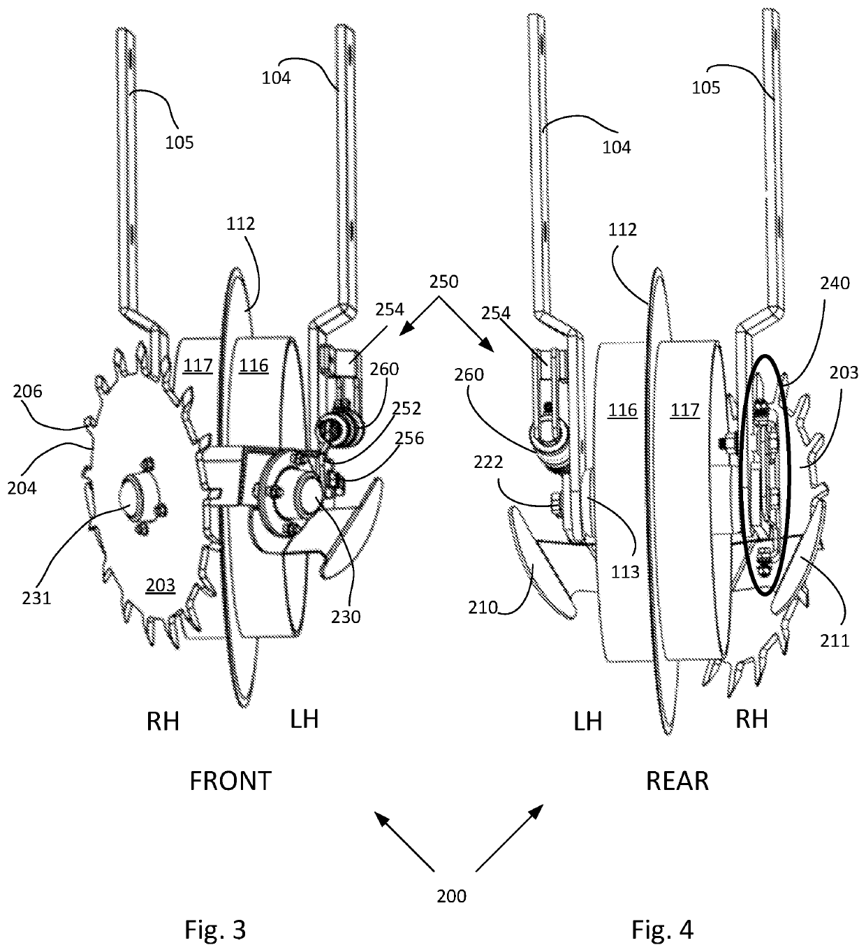
[0052]FIGS. 3 and 4 provide forward and rearward facing illustrations featuring the actuator and limiter components of the first embodiment strip till row cleaner invention with planter components removed for ease of illustration. As shown in FIGS. 3 and 4, row cleaner assembly 200 includes row cleaner travel limiter 240 and row cleaner angular displacement assembly 250 having actuator 260 operatively attached at one end to the row cleaner arm 220 and at an opposite end attached to and supported by goal post 104 at lower portion 110.

[0053]FIG. 3 is a front or forward-facing view of row cleaner 200 with the direction of travel of the row cleaner and strip till machine toward the viewer. From the front facing perspective the row cleaner and row cleaner wheels are shown in a substantial toe-in configuration. FIG. 4 is a rear or rearward-facing view of row cleaner 200 with the direction of travel being away from the viewer. Both figures show left-hand (LH) and right-hand (RH) sides of t...


PUM


Abstract

A row cleaner connected to a strip till machine and adapted to clear mulch and other debris encountered in strip or low till planting. A row cleaner frame assembly comprising: a pair of row cleaner arms and a pair of clearing wheels configured to have a toe-in alignment; wherein the pair of row cleaner arms share a common plane and are pivotally connected at a pair of pivot points common or close to the rotational axis of a cutting disc; wherein the cutting disc is disposed intermediate the pair of row cleaner arms; and wherein the row cleaner arms are configured to maintain the clearing wheels in a close-proximity to the cutting disc to provide stretch and cut row clearing operation with a biasing actuator for adjustability. An actuator pivotally adjusts the row cleaner assembly relative to the cutting disc. A pivot limiter restricts pivotal travel of the row cleaner to avoid damage to the actuator. A row closing section is provided and includes a lever adapted to adjust toe and / or camber of a closing wheel.

Description

FIELD OF THE INVENTION[0001]The present disclosure is generally applicable to the field of agricultural equipment, and more particularly for improved row cleaning and row closing in strip till farming applications.AUTHORIZATION PURSUANT TO 37 C.F.R. § 1.171 (d)(c)[0002]A portion of the disclosure of this patent document contains material which is subject to copyright and trademark protection. The copyright owner has no objection to the facsimile reproduction by anyone of the patent document or the patent disclosure, as it appears in the Patent and Trademark Office patent file or records, but otherwise reserves all copyrights whatsoever.BACKGROUND[0003]The background description includes information that may be useful in understanding the present invention. It is not an admission that any of the information provided herein is prior art or relevant to the presently claimed invention, or that any publication specifically or implicitly referenced is prior art.[0004]An example of a prior...

Claims


Application Information

Patent Timeline
Patent Type & Authority Applications(United States)
IPC IPC(8): A01B27/00A01B5/06A01B49/02A01B63/24
CPCA01B27/00A01B63/24A01B49/02A01B5/06A01B49/027A01B39/18
Inventor MARTIN, RONALD STEVE
Owner MARTIN RONALD STEVE
Why Eureka
Try Eureka