
Asymmetric solar receiver

a solar receiver and asymmetric technology, applied in the direction of solar heat collector details, solar heat collector mounting/support, light and heating apparatus, etc., can solve the problem that none of the prior art proposals combines the known asymmetry

Pending Publication Date: 2022-07-07
C DOS CONSULTING & ENG SL
View PDF0 Cites 0 Cited by
  • Summary
  • Abstract
  • Description
  • Claims
  • Application Information

AI Technical Summary

Benefits of technology

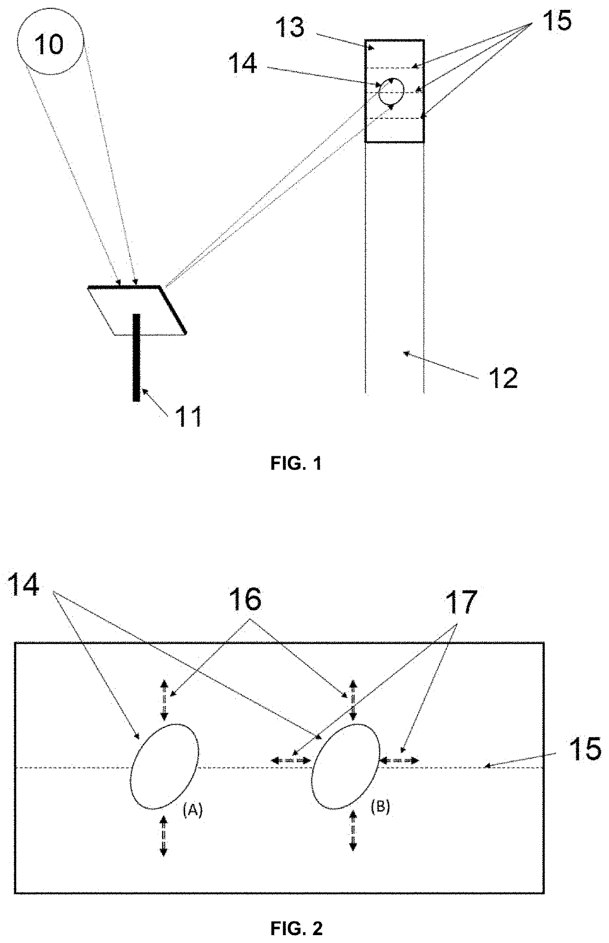
The invention describes an asymmetric solar receiver with variable geometry that improves efficiency and reduces energy losses. By using panels with different heights and optimizing the heliostat field configuration, the receiver can achieve higher energy concentration and performance. This results in a cost-effective and efficient solar energy production. The invention also provides a process for installation of a solar field, which includes calculating the distribution of heliostats to maximize energy flux performance over the receiver.

Problems solved by technology

However, none of the prior art proposals combines the known asymmetry, based on the balance between the effects due to the cosine factor and the distance, with also the use of an asymmetric north-south effective surface for the receiver as well.

Method used


Image

  • Asymmetric solar receiver
  • Asymmetric solar receiver
  • Asymmetric solar receiver

Examples


first embodiment

[0058]asymmetric solar receiver (13) according to the invention is depicted in FIG. 8a-8b. As shown in the figure, the panel structures (18) forming the receiver (13) comprise smaller area in one of the regions, where the panel structures are shortened in their upper and lower ends. Said asymmetric receiver (13) is installed in the tower (12) with its smaller area region oriented towards the south, while its bigger area region is oriented north. Thus, the number of heliostats (11) in the solar field can be rearranged for optimal efficiency compared to the case of a cylindrical receiver (13), so that a number of them will be located in the north field instead of in the south field.

[0059]Despite in these figures this receiver (13) is formed of vertical panel structures (18) wherein each panel structure is formed by only one panel, in different embodiments, each panel structure could also be divided into several unitary panels, so that the height of each panel structure is the result o...


PUM


Abstract

The invention relates to an asymmetric solar receiver suitable for its installation in heliostat tower solar power plants, wherein said receiver is adapted to cover at least an angular region of around a tower, and wherein the effective surface density of the receiver for receiving radiation varies depending on its orientation over the covered angular region thereof. The effective surface of said receiver is preferably made of one or more panels and, more preferably, the receiver comprises at least two panels, wherein at least one of the panels comprises a smaller height than the other panels. The invention also relates to a solar tower comprising said receiver, a solar field comprising said tower, a solar power plant comprising said solar field, and a process for installing a solar field.

Description

FIELD OF THE INVENTION[0001]The present invention relates to the technical field of thermodynamic concentrating solar power (CSP) technologies, concentrating solar power plants and, specifically, solar power tower concentrating technologies.BACKGROUND OF THE INVENTION[0002]Concentrating solar power (CSP) technology is an important alternative for providing clean and renewable electricity generation. CSP uses the heat of the sun, unrestricted and daily available energy source, that allows to reduce the greenhouse gas emissions in approximately 1 kg for each kW of electricity generated. The easy management, the dispatchability and the capacity to be adapted to the electric market demand makes CSP the most interesting technology among the renewable technologies and competitive with the fossil fuel power plants. Currently, there are four main CSP technologies, which are parabolic trough technology (PTC), linear Fresnel collector (LFC), Stirling / dish systems (SDC), and solar power tower ...

Claims


Application Information

Patent Timeline
IPC IPC(8): F24S20/20F24S23/70
CPCF24S20/20F24S2080/03F24S2023/87F24S23/70F24S70/65F24S25/10H02S20/10Y02E10/50
Inventor CARRASCOSA PÉREZ, MARCO ANTONIO
Owner C DOS CONSULTING & ENG SL
Learn More