Apparatus for generating x-ray radiation in an external magnetic field

a technology of external magnetic field and apparatus, which is applied in the manufacture of electrode systems, electric discharge tubes/lamps, and screens, etc., can solve the problems of optics impairment of the focusing of the electron beam emitted by the hot cathode, impair the service life of the hot cathode and hence the x-ray tube, and achieve enhanced field, reduced emitting surface, effect of reducing the surfa

Active Publication Date: 2018-05-01
SIEMENS HEALTHCARE GMBH
View PDF23 Cites 1 Cited by
  • Summary
  • Abstract
  • Description
  • Claims
  • Application Information

AI Technical Summary

Benefits of technology

[0008]It is an object of the present disclosure to specify an apparatus for generating x-ray radiation operable in an external magnetic field and which may generate a high electric current, without there being a risk of destroying the cathode or a reduction in the service life of the cathode and without the image quality being impaired.
[0014]Expediently, the electron emitter has a convex surface in the cross section in relation to an axial direction of extent, wherein the convex surface extends exclusively in the direction of the anode and represents the electron emitter. This is accompanied by a reduction in the emitting surface of the electron emitter in comparison with a filament of a hot cathode. This is accompanied by an electron current in the direction of the anode that is uninfluenced by the external magnetic field because it is provided that only electrons in the direction of the anode may emerge from the electron emitter. In particular, a reduction in the emitting surface is also avoided in comparison with a filament of a hot cathode because only the front side of the electron emitter contributes to the electron current.
[0015]In the cross section in relation to an axial direction of extent, the electron emitter may have the form of a semi-cylinder. In principle, the convex surface may also be realized by other cross-sectional forms of the electron emitter. The form of a semi-cylinder facilitates a convex surface that exclusively extends in the direction of the anode. In particular, this form renders possible an enhanced field on the area of the semi-cylinder, in particular over the entire linear profile thereof, as result of which the electron emergence is simplified.

Problems solved by technology

Likewise, the focusing of the electron beam emitted by the hot cathode is impaired by the optics that are characterized by electric fields.
However, such an increase in the heating temperature impairs the service life of the hot cathode and hence of the x-ray tube.

Method used


Image

  • Apparatus for generating x-ray radiation in an external magnetic field
  • Apparatus for generating x-ray radiation in an external magnetic field

Examples


Embodiment Construction

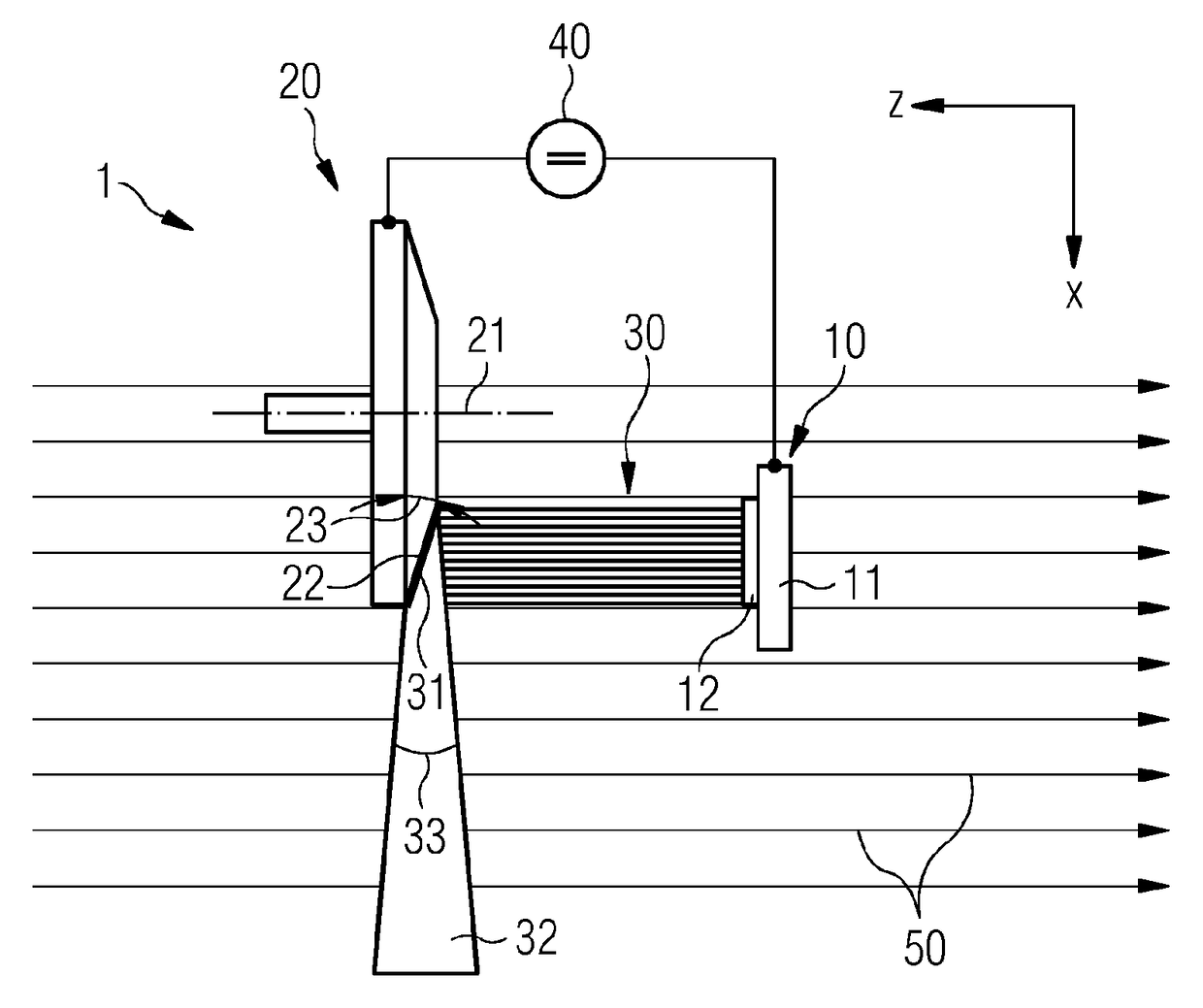
[0023]FIG. 1 depicts a schematic illustration of an apparatus 1 for generating x-ray radiation 32. The apparatus 1 includes a cathode 10 and an anode 20 that is rotatable about an axis of rotation 21 (a so-called rotating anode). The anode 20 may also be embodied as a stationary anode. By way of a DC voltage source 40, which is interconnected between the cathode 10 and the anode 20, an electric voltage at a given level is applied between said cathode and said anode. As a result, an electric field that is directed from the anode in the direction of the cathode arises. The apparatus 1 is arranged in an external magnetic field 50 that is generated by a magnetic field device not illustrated in any more detail. The magnetic field lines of the magnetic field 50 and the electric field lines of the electric field, which is generated between the anode 20 and the cathode 10, extend largely collinearly. This means that the field lines of the electric field correspond to the field lines of the ...


PUM


Abstract

An apparatus is provided for generating X-ray radiation in an outer magnetic field, which may be generated by a magnetic field device. The apparatus includes a cathode configured to generate an electron beam and an anode configured to retard the electrons of the electron beam and generate an X-ray beam. The apparatus further includes a device configured to generate an electric field orientated from the anode in the direction of the cathode and substantially collinear to the outer magnetic field, wherein the cathode, as an electron emitter, includes a cold cathode that passively provides free electrons by field emission.

Description

[0001]The present patent document is a § 371 nationalization of PCT Application Serial Number PCT / EP2016 / 050862, filed Jan. 18, 2016, designating the United States, which is hereby incorporated by reference, and this patent document also claims the benefit of DE 10 2015 201 375.8, filed Jan. 27, 2015, which is also hereby incorporated by reference.TECHNICAL FIELD[0002]The disclosure relates to an apparatus for generating x-ray radiation in an external magnetic field generable by a magnetic field device.BACKGROUND[0003]An apparatus for generating x-ray radiation includes a cathode for generating an electron beam and an anode for decelerating the electrons of the electron beam and for generating an x-ray beam. Moreover, the apparatus includes a device for generating an electric field that is directed from the cathode in the direction of the anode.[0004]In such an apparatus, the x-ray radiation arises from energetic transitions in the electron shells of atoms or molecules and from the ...

Claims


Application Information

Patent Timeline
Patent Type & Authority Patents(United States)
IPC IPC(8): H01J1/304H01J3/02H01J31/08H01J35/14H01J9/02H01J35/10H01J35/06
CPCH01J1/304H01J3/021H01J9/025H01J35/14H01J35/065H01J35/10H01J31/08
Inventor GEISLER, ANDREASGO.BETA.MANN, SVETLANAHEID, OLIVER
Owner SIEMENS HEALTHCARE GMBH
Why Eureka
Try Eureka