Symbol judgement apparatus and symbol judgement method

a symbol determination and symbol technology, applied in the field of symbol determination devices and symbol determination methods, can solve the problems of signal quality degradation associated with increasing transmission capacity, affecting the scale enlargement of dc at a single site, and affecting the effect of device band restrictions and wavelength dispersion, so as to achieve the effect of suppressing the amount of computation

Active Publication Date: 2022-07-14
NIPPON TELEGRAPH & TELEPHONE CORP
View PDF6 Cites 0 Cited by
  • Summary
  • Abstract
  • Description
  • Claims
  • Application Information

AI Technical Summary

Benefits of technology

[0043]According to the present invention, an increase in the amount of computation can be suppressed even in a case where the symbol multi-level degree increases when performing a determination of a transmission symbol from a reception signal sequence.

Problems solved by technology

Due to communication traffic increase, it is expected that the scale enlargement of DC at a single site becomes difficult.
As a challenge for further capacity enlargement, signal quality degradation associated with increase in the transmission capacity, that is, the impact of device band restrictions and wavelength dispersion becomes obvious.
For example, as illustrated in FIG. 16, when the transmission capacity increases and the used band thus increases, there is a problem that the frequency region 501 (hatched region of diagonal lines) is lost due to the device band restrictions.
However, such devices are expensive and the cost required for the device increases, and thus, from an economical point of view, this approach is preferably avoided.
However, in a case of using low cost narrow band devices, problems caused by band restrictions, inter-symbol interference due to wavelength dispersion, and the like associated with increase of communication speed as described above need to be solved.

Method used


Image

  • Symbol judgement apparatus and symbol judgement method
  • Symbol judgement apparatus and symbol judgement method
  • Symbol judgement apparatus and symbol judgement method

Examples


first embodiment

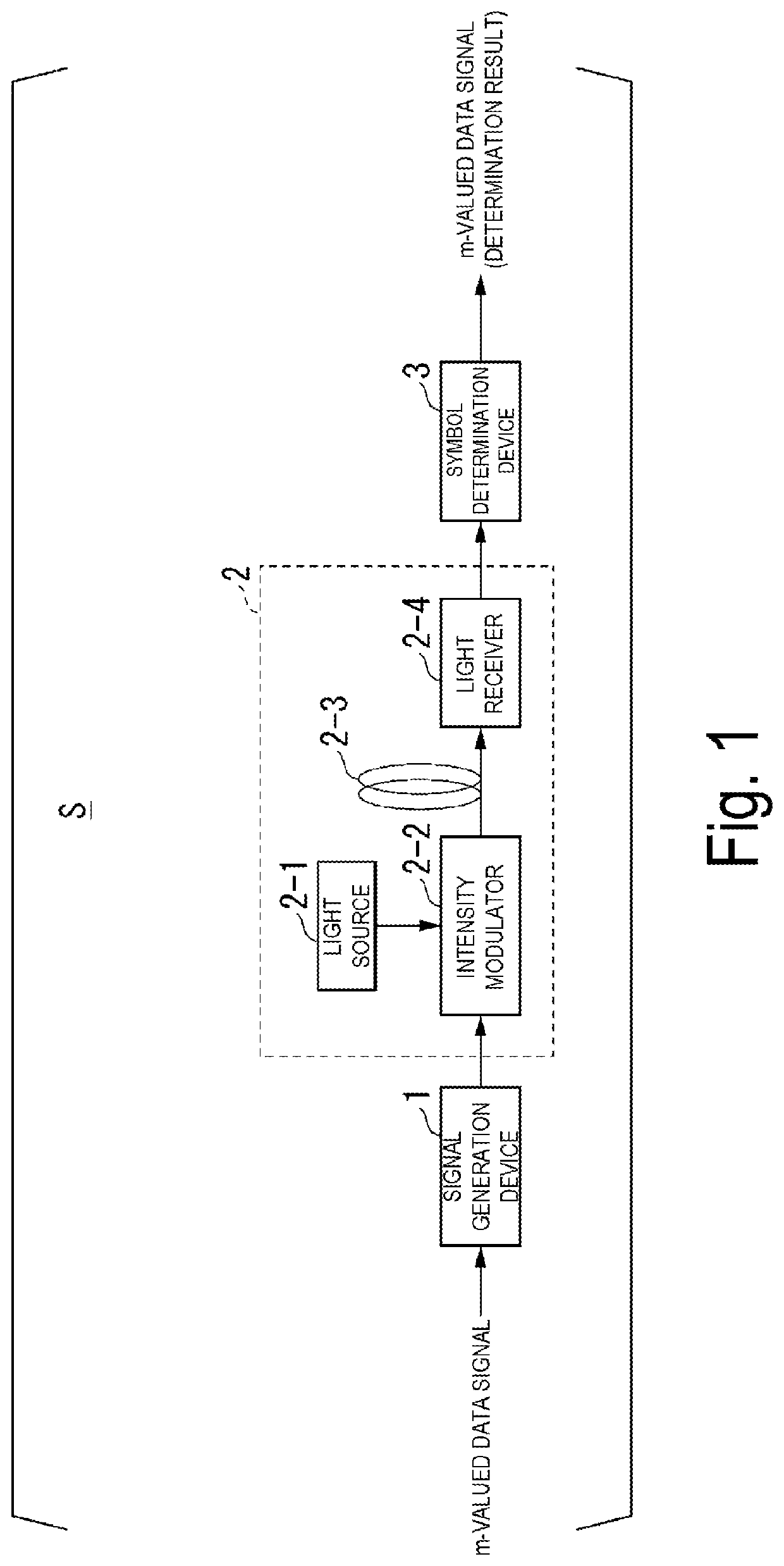
[0066]Embodiments of the present invention will be described below with reference to the drawings. FIG. 1 is a block diagram illustrating a configuration of a communication system S according to a first embodiment. The communication system S includes a signal generation device 1, a transmission line 2, and a symbol determination device 3.

[0067]The signal generation device 1 and the transmission line 2 have the same configurations as the signal generation device 1 and the transmission line 2 provided in the conventional communication system 100 illustrated in FIG. 18. The signal generation device 1 takes in an m-valued data signal provided from the outside. m is the symbol multi-level degree, for example, an integer of 2 or greater. Each symbol is represented by numbers and symbols. For example, in the case of m=8, respective symbols are represented by the number [0, 1, 2, 3, 4, 5, 6, 7]. The signal generation device 1 generates a transmission signal sequence {st} of an electrical si...

second embodiment

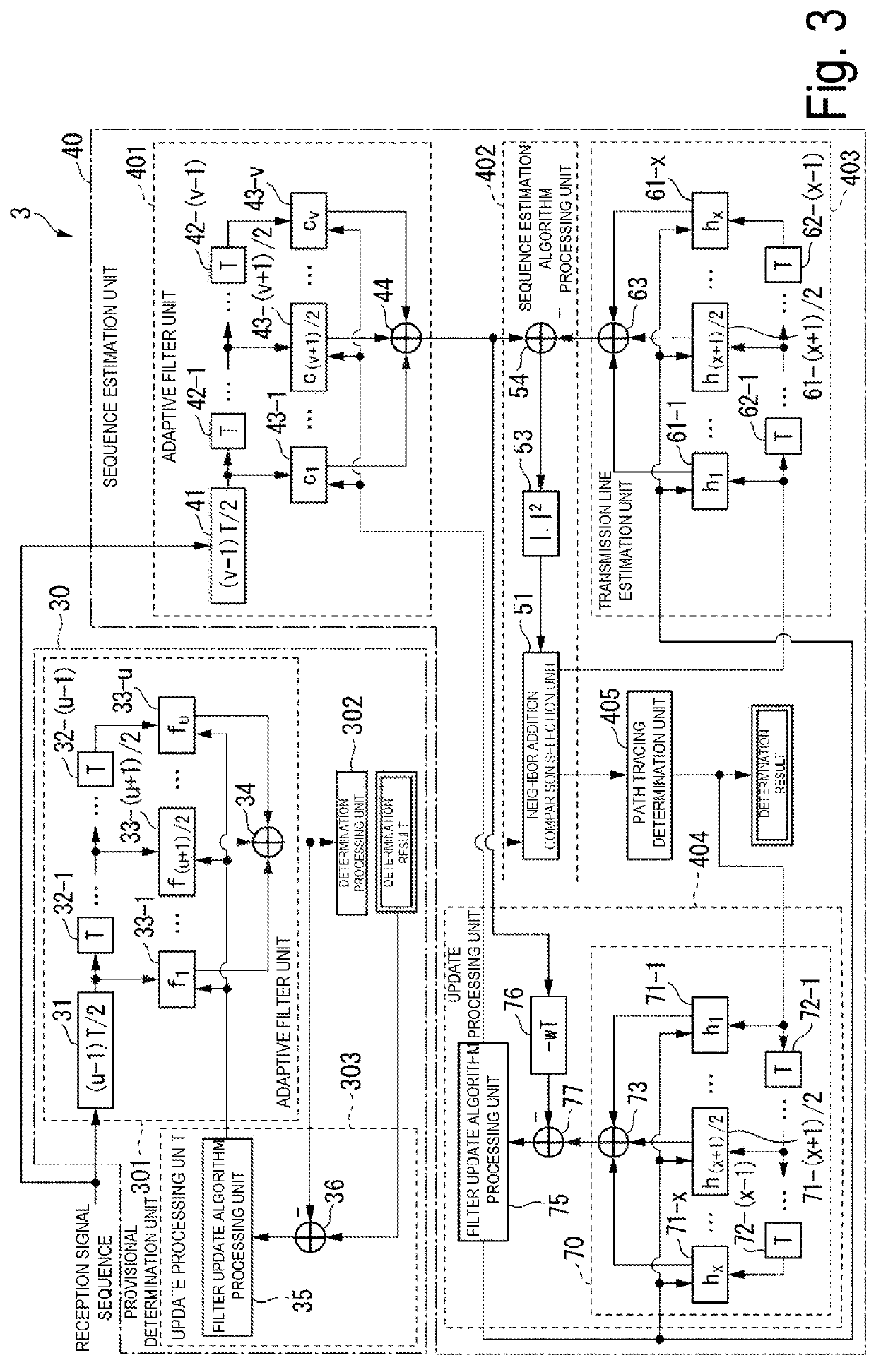
[0144]FIG. 10 is a block diagram illustrating an internal configuration of a symbol determination device 3a according to the second embodiment. FIG. 11 is a block diagram illustrating a detailed internal configuration of the symbol determination device 3a according to the second embodiment. In the second embodiment, the same reference signs will be assigned to the same components as those in the first embodiment, and hereinafter, different components will be described.

[0145]As illustrated in FIG. 10, the symbol determination device 3a includes a provisional determination unit 30 and a sequence estimation unit 40a. The sequence estimation unit 40a includes an adaptive filter unit 401a, a sequence estimation algorithm processing unit 402, a transmission line estimation unit 403, an update processing unit 404, and a path tracing determination unit 405.

[0146]The input end of the adaptive filter unit 401a is connected to the output end of the adaptive filter unit 301 of the provisional d...


PUM


Abstract

A device generates a symbol sequence by performing adaptive equalization by an estimation inverse transfer function of a transmission line on a reception signal sequence extracted from the transmission line, and performing provisional determination on the symbol sequence generated; generates a plurality of the symbol sequences indicating transmission line states in a range of a provisional determination symbol provisionally determined and nearby symbols of the provisional determination symbol; generates, based on the plurality of the symbol sequences indicating the transmission line states generated and an estimation transfer function of the transmission line, an estimation reception symbol sequence for each of the transmission line states; calculates a metric between the symbol sequence obtained from the reception signal sequence and each of a plurality of the estimation reception symbol sequences; selects a most likelihood estimation reception symbol sequence of the plurality of the estimation reception symbol sequences, based on the calculated metric, the provisional determination symbol, and the nearby symbols of the provisional determination symbol; and determines a transmission symbol sequence.

Description

TECHNICAL FIELD[0001]The present invention relates to a symbol determination device and a symbol determination method.BACKGROUND ART[0002]The traffic transferred by backbone networks of the Internet continues to increase by the recent rapid spread of smartphones and tablets, and increases in rich contents, such as high definition video distribution services. The utilization of cloud services in enterprises is also increasing. From these trends, it is expected that network traffic in data centers (hereinafter referred to as “DCs”) and between DCs is increasing at an annual rate of approximately 1.3 times.[0003]The Ethernet (trade name) is currently, mainly introduced to a connection scheme in DCs and between DCs. Due to communication traffic increase, it is expected that the scale enlargement of DC at a single site becomes difficult. Thus, the need for DC-to-DC cooperation will be higher than before in the future, and an additional increase in traffic transmitted and received between...

Claims


Application Information

Patent Timeline
Patent Type & Authority Applications(United States)
IPC IPC(8): H04L27/01
CPCH04L27/01H03M13/41H04L25/03248H04L2025/03471
Inventor TANIGUCHI, HIROKINAKAMURA, MASANORIYAMAMOTO, SHUTOMASUDA, AKIRAKISAKA, YOSHIAKI
Owner NIPPON TELEGRAPH & TELEPHONE CORP
Why Eureka
Try Eureka