
Device for a subscriber station of a serial bus system and method for communication in a serial bus system

a serial bus system and subscriber station technology, applied in bus networks, digital transmission, data switching networks, etc., can solve the problems of insufficient accuracy of signal rxd, network speed still considerably lower than it is today, and low useful data length of up to 64 bytes currently achieved by can fd for some applications

Pending Publication Date: 2022-07-28
ROBERT BOSCH GMBH
View PDF0 Cites 1 Cited by
  • Summary
  • Abstract
  • Description
  • Claims
  • Application Information

AI Technical Summary

Benefits of technology

The present invention provides a device and method for communication in a serial bus system that can solve problems of high data rate and increased useful data per frame with great flexibility and error robustness. The device can detect transmission conflicts and interfere with or interrupt the transmission of other subscriber stations as necessary. This allows for efficient communication even at high data rates and an increase in the number of useful data per frame. The method offers the same advantages as the device and subscriber station.

Problems solved by technology

However, such a network still has a considerably lower speed than a data transmission in a 100 base T1 ethernet, for example.
In addition, the useful data length of up to 64 bytes currently achieved by CAN FD is too low for some applications.
Such a direct comparison would require a measurement of the signal propagation time and the intermediate storage of a sequence of the last values of transmit message Tx for the evaluation by a protocol control unit and would therefore be quite complex.
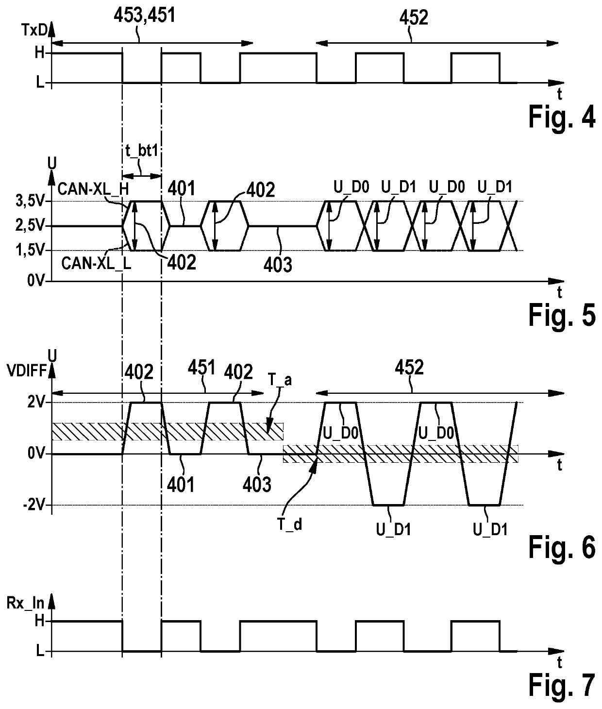
This also applies if a superposition of driven signals occurs on the bus so that “analog” levels come about on the bus and a transmission conflict is no longer reliably detectable by comparing transmit signal TXD and receive signal RXD because the resulting receive signal RXD is no longer accurately predictable.

Method used


Image

  • Device for a subscriber station of a serial bus system and method for communication in a serial bus system
  • Device for a subscriber station of a serial bus system and method for communication in a serial bus system
  • Device for a subscriber station of a serial bus system and method for communication in a serial bus system

Examples


Embodiment Construction

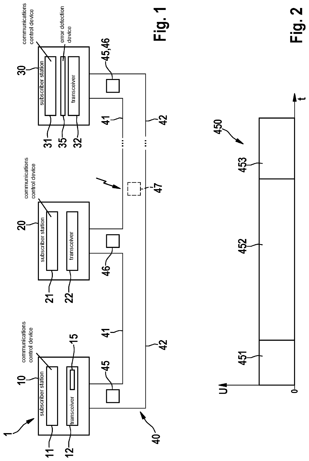
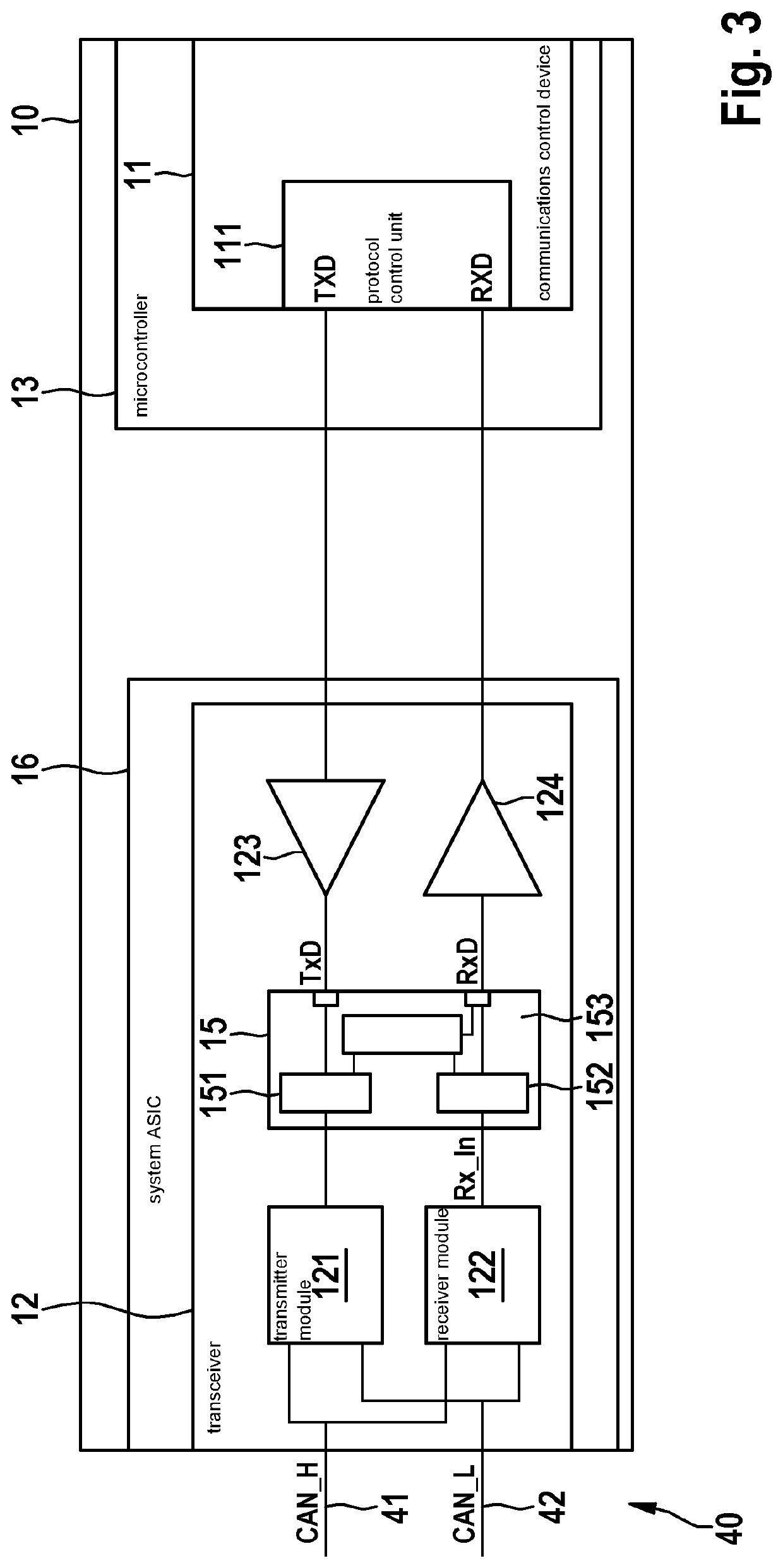
[0049]As an example, FIG. 1 shows a bus system 1, which in particular is basically configured for a CAN bus system, a CAN FD bus system, a CAN XL bus system and / or variations thereof as will be described in the following text. Bus system 1 may be used in a vehicle, in particular a motor vehicle, an airplane, etc. or in a hospital, etc.

[0050]In FIG. 1, bus system 1 has a multitude of subscriber stations 10, 20, 30, which are connected to a bus 40 in each case via a first bus conductor 41 and a second bus conductor 42. Bus conductors 41, 42 may also be referred to as CAN_H and CAN_L or CAN-XL_H and CAN-XL_L and are used for an electrical signal transmission after coupling the differential levels or generating recessive levels for a signal in the transmission state. Messages 45, 46 in the form of signals are serially transmittable via bus 40 between the individual subscriber stations 10, 20, 30. If an error occurs during the communication on bus 40, as illustrated by the jagged black b...


PUM


Abstract

A device and method for a serial bus system. The device has a transmit signal analysis module for counting edges of a transmit signal to be transmitted on a bus of the bus system; a receive signal analysis module for counting edges of a receive signal generated from a signal transmitted on the bus because of the transmit signal; and an evaluation module for evaluating the difference that results from a comparison of the edges counted by the transmit signal analysis module and the edges counted by the receive signal analysis module. If the signal propagation time on the bus is greater than the bit time of the receive signal, the evaluation module signals whether the amount of the difference is less than or equal to a predefined value or whether the amount of the difference is greater than the predefined value, the predefined value being greater than zero.

Description

FIELD[0001]The present invention relates to a device for a subscriber station of a serial bus system and to a method for communication in a serial bus system which operates at a high data rate and with great fault robustness.BACKGROUND INFORMATION[0002]At present, bus systems are frequently used in the communication between sensors and control units. Especially in vehicles, a bus system is often used in which data are transmitted as messages based on the ISO 11898-1:2015 standard as a protocol specification using CAN FD. The messages are transmitted between the bus subscribers of the bus system, e.g., a sensor, control unit, transmitter, and others.[0003]It is frequently desired that technical systems offer more and more functions. This applies especially to vehicles. The increasing number of functions also causes an increase in the data traffic on the bus system. In addition, it is also often required that the data be transmitted from the transmitter to the receiver more rapidly th...

Claims


Application Information

Patent Timeline
Patent Type & Authority Applications(United States)
IPC IPC(8): H04L12/413H04L12/40
CPCH04L12/413H04L2012/40215H04L12/4013H04L12/40H04L12/4135H04L2012/40273
Inventor HARTWICH, FLORIANMUTTER, ARTHURWALKER, STEFFEN
Owner ROBERT BOSCH GMBH
Learn More