

System and method for treating haemorrhagic fluid for autotransfusion
a technology of autotransfusion and haemorrhagic fluid, which is applied in the direction of suction devices, blood transfusion, medical devices, etc., can solve the problems of limiting the haemolysis of patients, unable to achieve high platelet recovery rate by this method, and unable to achieve high platelet recovery ra
Pending Publication Date: 2022-08-04
I SEP
View PDF0 Cites 0 Cited by
- Summary
- Abstract
- Description
- Claims
- Application Information
AI Technical Summary
Benefits of technology
Problems solved by technology
This dilution in a carrier fluid also decreases the contact of the red blood cells with air, thus greatly limiting their haemolysis.
The recovered blood must next be transfused to the patient in order to compensate the loss of blood volume, but important problems are encountered.
A high recovery rate of platelets is thus impossible by this method.
This coat is thus unsuitable for direct transfusion.
Further, when the centrifugation is too strong, there is going to be elimination of the platelets and thus an impoverishment of the quality of the concentrate to transfuse.
Centrifugation, a known and widely used mechanism in autotransfusion, also leads to slight mechanical haemolysis.
This direct loss of cells of interest, directly contributing to primary hemostatis (platelet aggregation at the level of the wound), is problematic during an operation as may easily be understood.
However, such systems have a certain number of drawbacks, notably in terms of efficiency.
Platelets also have high adhesive power after activation and have a tendency to adsorb on the surface of the membranes or plasmatic proteins and clog up the membranes.
Tangential filtration is subjected to a quantity of material being able to pass through the membrane per unit of time, which limits in general the speed of treatment.
However, a patient suffering from a massive haemorrhage cannot have his loss of chance coefficient increased on account of a longer filtration time.
Method used
View moreImage
Smart ImageViewing Examples

Examples
first embodiment
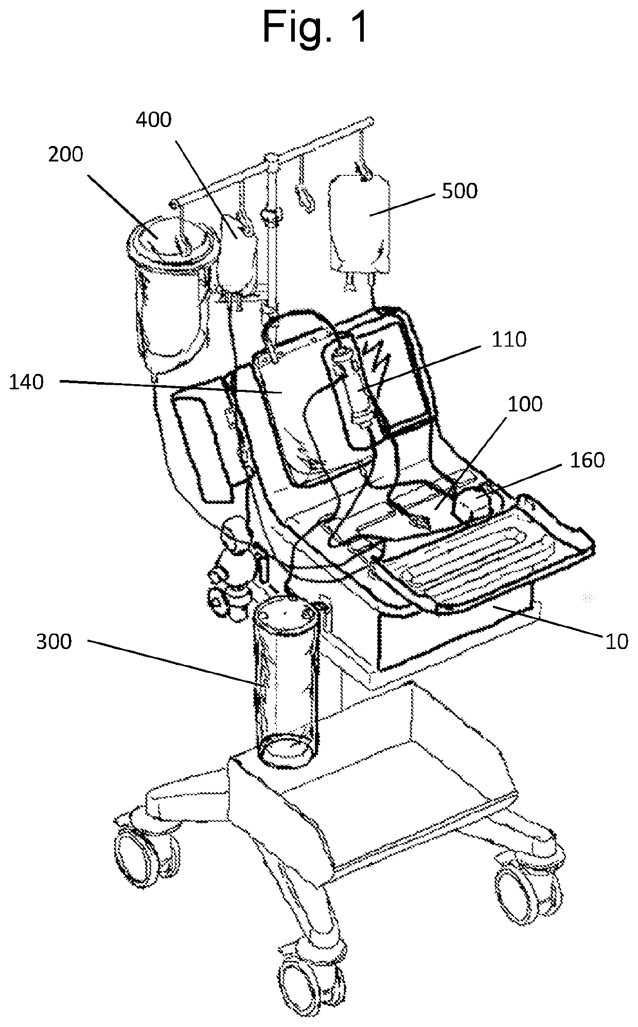
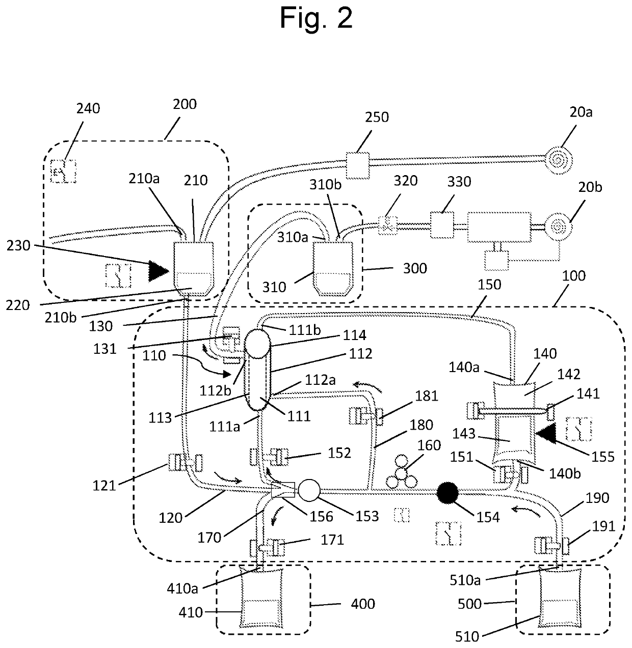
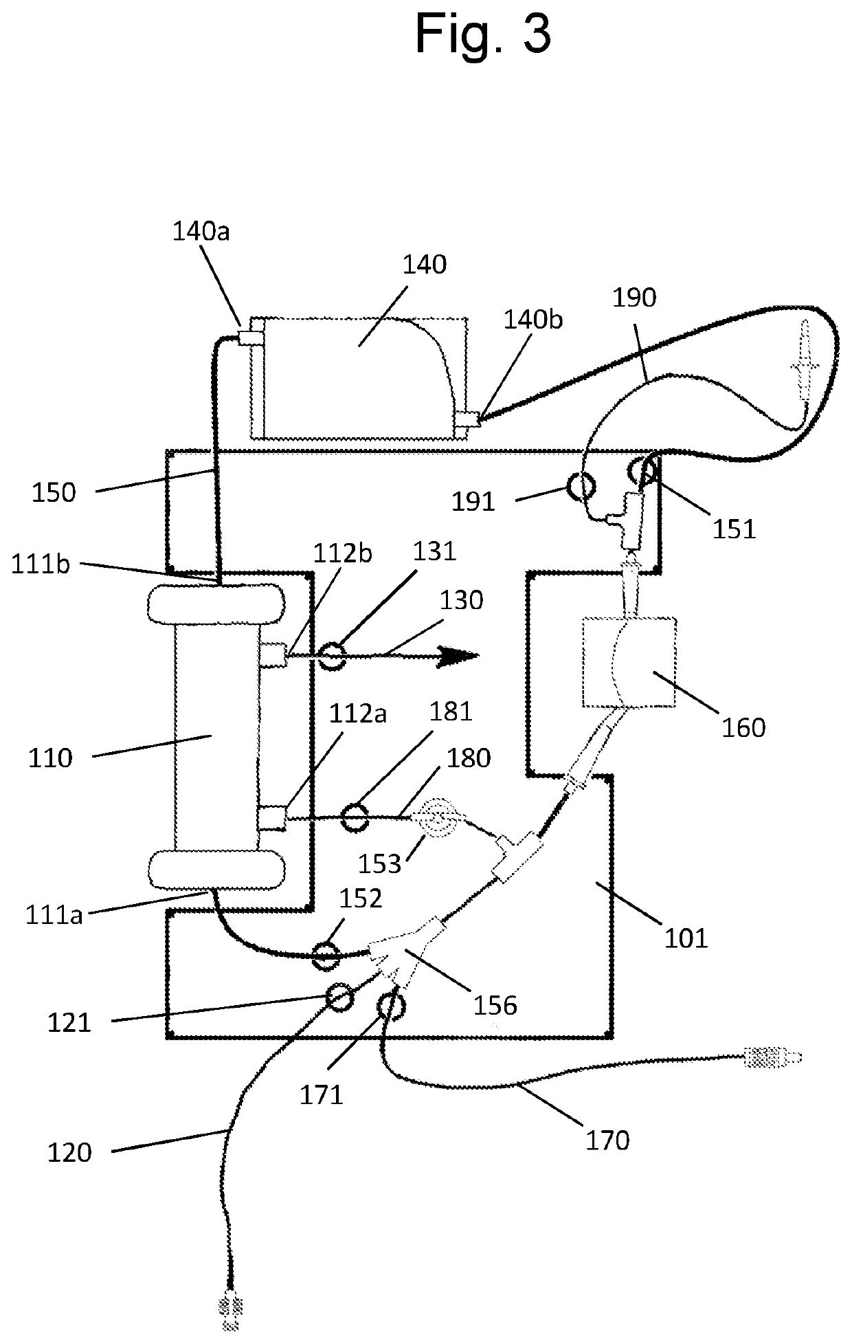
[0119]FIG. 3 is a representation of a treatment unit of a treatment system, according to the first arrangement;
second embodiment
[0120]FIG. 4 is a representation of a treatment unit of a treatment system, according to the first arrangement;
[0121]FIG. 5 is a schematic representation of a treatment bag for the treatment unit of a treatment system according to the invention;
[0122]FIG. 6 is a schematic representation of a second arrangement of fluidic connections for the treatment system according to the invention;
[0123]FIG. 7 is a schematic representation illustrating an exemplary positioning of an additional prefiltration device for the treatment system described.
Login to View More PUM
 Abstract
A method and system for treating, by filtration, haemorrhagic fluid contained in a container with a view to subsequent autotransfusion, including at least one step of concentrating by filtration said haemorrhagic fluid in order to increase the concentration of red blood cells in the haemorrhagic fluid to reach a target haematocrit level while at the same time removing from the haemorrhagic fluid a filtrate comprising compounds not desired for autotransfusion, further including:a preliminary step of measuring the haematocrit level of the haemorrhagic fluid; anda dilution step consisting in adding to the volume of haemorrhagic fluid to be treated a determined volume of dilution fluid, the determined volume of dilution fluid being calculated as a function of the measured haematocrit level of the haemorrhagic fluid and the target haematocrit level.
Description
FIELD OF INVENTION[0001]The present invention relates to the field of the treatment of haemorrhagic fluid such as blood to carry out an autotransfusion on a patient, notably in the course of a surgical intervention.PRIOR ART[0002]Autotransfusion or autologous transfusion, namely the transfusion into a patient of his or her own blood, is increasingly practiced during surgical interventions since it avoids the incompatibilities that may exist with homologous or allogenic transfusions, that is to say transfusions from the blood of another person, and it notably prevents the transmission of infectious diseases.[0003]In the case of intraoperative autotransfusion, it is advisable to be able to transfuse blood collected directly from the patient almost continuously, that is to say by limiting dead times notably due to the treatment of the blood, this treatment being carried out with a treatment device independently of the patient. Yet, during the collection, in a known manner, this blood a...
Claims
Login to View More Application Information
Patent Timeline
 Patent Type & AuthorityApplications(United States)
IPC IPC(8): A61M1/02
CPCA61M1/0281A61M2230/207A61M2202/0429A61M1/0218A61M2205/7554A61M2205/3334A61M2205/3306A61M1/342
InventorGADRAT, FRANCISDECOUTURE, BENOÎTCHOLLET, STÉPHANEFOREST-VILLEGAS, PATRICIAPICOT, SYLVAIN
OwnerI SEP