
Dehumidification system

Pending Publication Date: 2022-08-04
ITSWA
View PDF0 Cites 0 Cited by
  • Summary
  • Abstract
  • Description
  • Claims
  • Application Information

AI Technical Summary

Benefits of technology

The present invention provides a dehumidification system that reduces energy consumption by separating airflow and using a desiccant air conditioner. The system has a first closed loop pipeline for air circulating through the absorption zone of the dehumidification rotor and the dry room, and a second closed loop pipeline for air circulating through the regeneration zone of the dehumidification rotor, the purge zone, and the desiccant air conditioner. The desiccant air conditioner has a post-regeneration exhaust pipeline and an outdoor air intake pipeline. When the dry room is not ventilated, air circulates independently in each of the two closed loop pipelines, resulting in less moisture absorption and energy consumption. When the dry room is ventilated, the system dehumidifies the outdoor air and supplies it to the dry room as dry air, which further reduces energy consumption.

Problems solved by technology

Thus because it is necessary to decrease the dew point temperature of mixed air of such outdoor air and the air in the dry room at once, a lot of electric power is consumed.
That is to say, the conventional dehumidification system consumes more electric power to dehumidify the outdoor air taken in the dry room (dehumidification system) rather than the air in the dry room, and in this respect, the conventional dehumidification system has the disadvantage of very inefficient use of energy because of wasting a lot of electric power.

Method used


Image

  • Dehumidification system
  • Dehumidification system

Examples


Embodiment Construction

[0030]A preferred embodiment of the present invention will be explained below with reference to accompanying drawings.

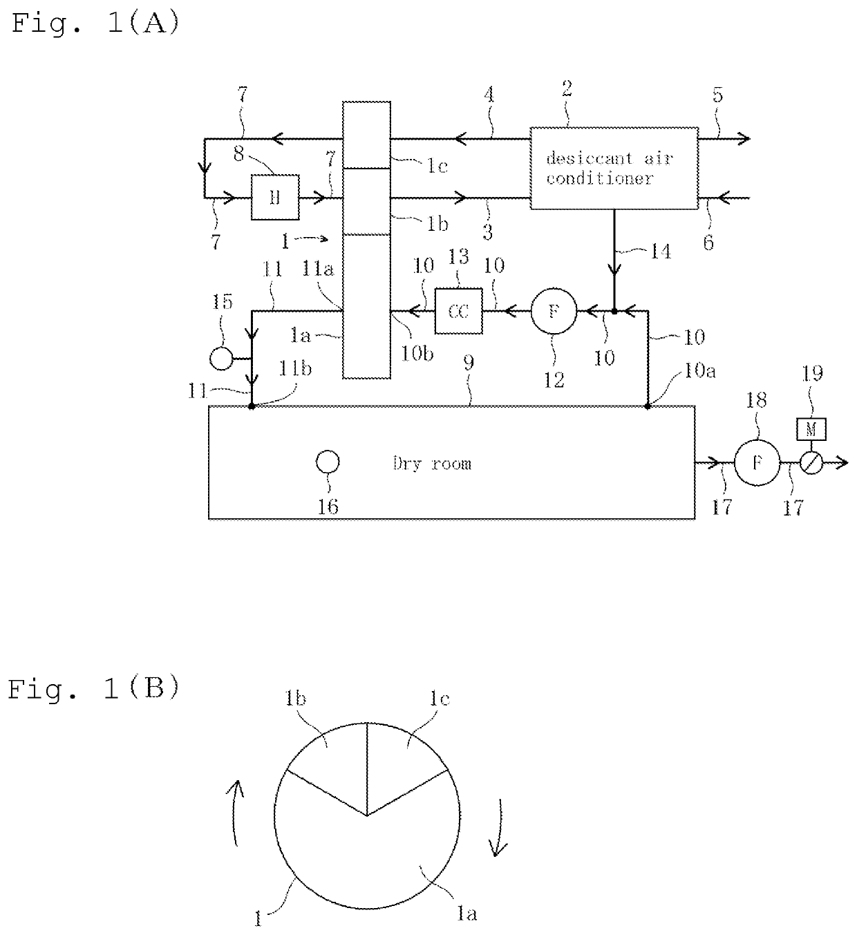
[0031]FIG. 1(A) is a diagram showing a schematic configuration of a dehumidification system according to an embodiment of the present invention, and FIG. 1(B) is a schematic cross-sectional view of a dehumidification rotor of the dehumidification system shown in FIG. 1(A).

[0032]As shown in FIG. 1, according to the present invention, a first dehumidification rotor 1 having at least an absorption zone 1a, a regeneration zone 1b and a purge zone 1c in order along a rotation direction of the first dehumidification rotor 1, a desiccant air conditioner 2, and a first post-regeneration exhaust pipeline 3 supplying post-regeneration exhaust from the regeneration zone 1b of the first dehumidification rotor 1 to the desiccant air conditioner 2 are provided. Further, a first purge air supply pipeline 4 supplying purge air from the desiccant air conditioner 2 to the purge zone 1...


PUM


Abstract

A dehumidification rotor 1, a desiccant air conditioner 2, a first post-regeneration exhaust pipeline 3 supplying post-regeneration exhaust from a regeneration zone 1b of the dehumidification rotor, a purge air supply pipeline 4 supplying purge air from the desiccant air conditioner to a purge zone of the dehumidification rotor, and a regeneration air supply pipeline 7 supplying regeneration air from the purge zone to the regeneration zone are provided. The desiccant air conditioner comprises a second post-regeneration exhaust pipeline 5 and an outdoor air intake pipeline 6. An indoor air intake pipeline supplying air of a dry room 9 to an absorption zone 1a of the dehumidification rotor 10, a first dry air supply pipeline 11 supplying dry air from the absorption zone to the dry room, and a second dry air supply pipeline 14 supplying dry air from the desiccant air conditioner to the indoor air intake pipeline are provided.

Description

TECHNICAL FIELD[0001]The present invention relates to a dehumidification system, particularly to a dehumidification system used to maintain a low dew point environment in a dry room.BACKGROUND ART[0002]A low dew point environment is required for developing and manufacturing lithium-ion batteries and organic EL displays.[0003]A dry room is widely used as a device for generating and maintaining the low dew point environment, and the dry room has a dehumidification system for controlling the dew point in the dry room.[0004]A conventional dehumidification system of this kind comprises a dehumidification rotor. An absorption zone of the dehumidification rotor is connected to the dry room through an indoor air intake pipeline at an input side thereof and an output side of the absorption zone is connected to the dry room through a dry air supply pipe, so that an air circulation line is composed of the dry room, the indoor air intake pipeline, the absorption zone of the dehumidification rot...

Claims


Application Information

Patent Timeline
IPC IPC(8): B01D53/06B01D53/26F24F3/14
CPCB01D53/06B01D53/261F24F3/1411F24F2003/144B01D2259/4009B01D2259/402B01D2259/4508B01D2257/80B01D53/265F24F3/1423F24F3/14F24F2003/1446F24F2003/1464F24F2003/1458F24F2203/1036
Inventor OGASAHARA, MINORU
Owner ITSWA
Features
  • Generate Ideas
  • Intellectual Property
  • Life Sciences
  • Materials
  • Tech Scout
  • Unparalleled Data Quality
  • Higher Quality Content
  • 60% Fewer Hallucinations
Learn More