
Systems and methods for deploying hydroelectric energy systems

a hydroelectric energy system and hydroelectric technology, applied in the field of hydroelectric energy systems, can solve the problems of skewing the levelized cost of electricity (lcoe) of such turbines, affecting the use of special purpose vessels, and high costs associated with the deployment of turbines and the foundation structures used to support turbines

Pending Publication Date: 2022-08-04
OCEANA ENERGY
View PDF0 Cites 2 Cited by
  • Summary
  • Abstract
  • Description
  • Claims
  • Application Information

AI Technical Summary

Benefits of technology

This patent describes a method and system for deploying payloads at subaquatic locations using a submersible aquatic vehicle. The vehicle carries the payload and can transition from a first position to a second position to deploy the payload at the desired location. This technique allows for more efficient and precise deployment of various subaquatic payloads, such as hydroelectric turbines and other components of hydroelectric energy systems. The method and system can also be utilized for other subaquatic payloads, such as sensors and monitoring devices.

Problems solved by technology

Although recent developments in hydroelectric energy and turbine technology have reduced the building and maintenance costs of such systems, the costs associated with deployment of the turbines and the foundation structures, or spires, used to support the turbines can be relatively high, which in turn can skew the Levelized Cost of Electricity (LCOE) from such turbines.
Consequently, the relatively high total system LCOE of hydroelectric turbines can make their use less feasible than other traditional, less expensive power sources (i.e., power sources that may have a lower total system LCOE), such as, petroleum, natural gas, and coal systems.

Method used


Image

  • Systems and methods for deploying hydroelectric energy systems
  • Systems and methods for deploying hydroelectric energy systems
  • Systems and methods for deploying hydroelectric energy systems

Examples


Embodiment Construction

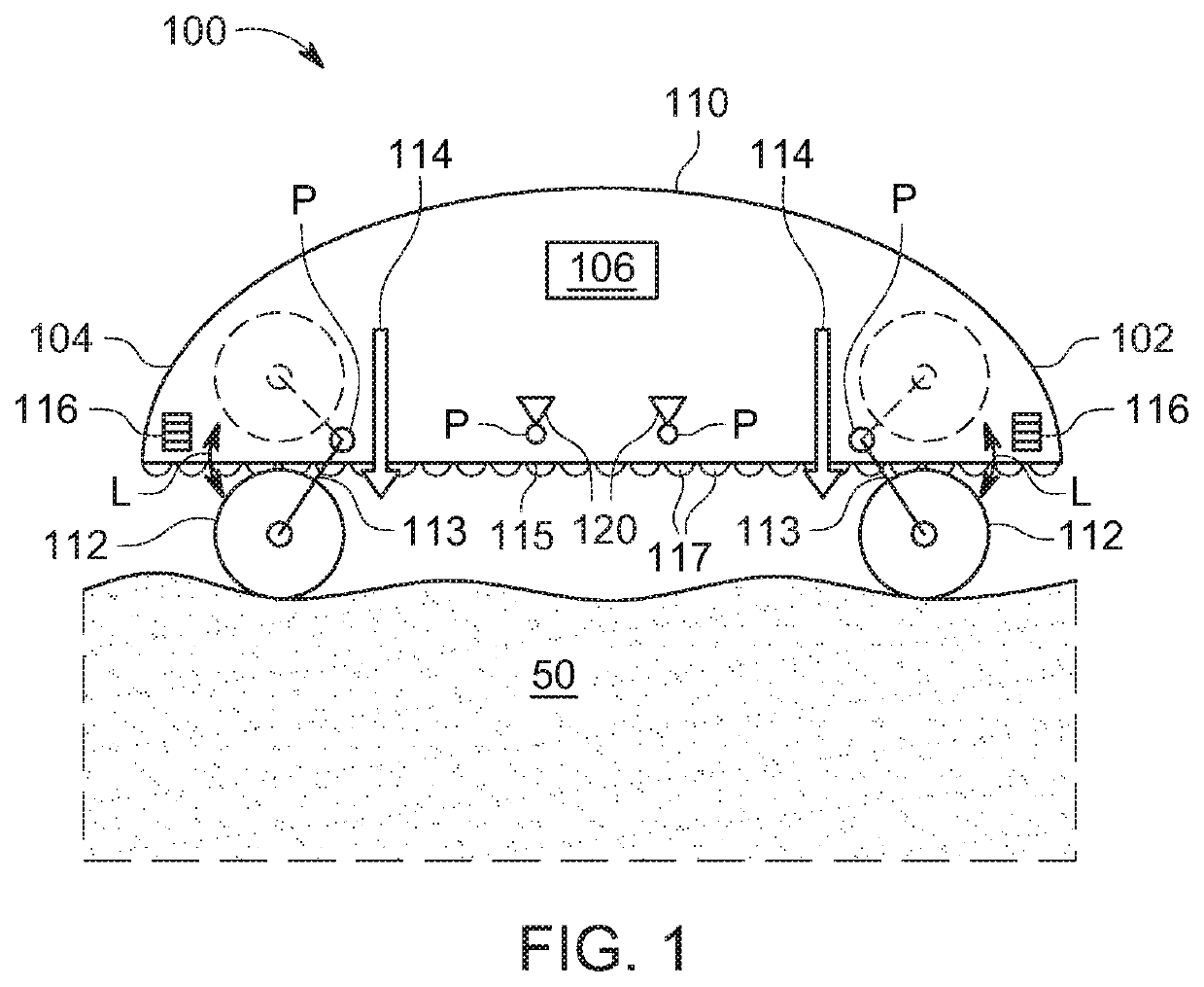
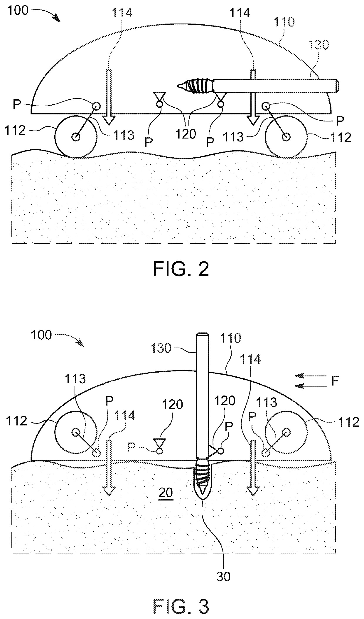
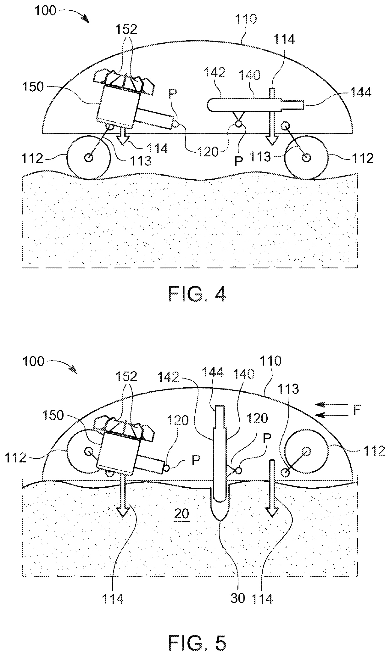
[0051]To more efficiently deploy subaquatic payloads, such as, for example, those associated with hydroelectric energy systems, the systems and methods of the present disclosure may utilize submersible aquatic vehicles that can carry and deploy a variety of payloads, such as foundation structures and hydroelectric turbines for hydroelectric energy systems, by submersing the vehicle and driving to a deployment subaquatic site directly from shore or after being lowered from a watercraft (e.g., a floating vessel).

[0052]The present disclosure contemplates, for example, systems and methods for deploying hydroelectric energy systems that include a hydroelectric turbine that is configured to generate electricity from the current in a moving body of water (e.g., a river or ocean current) or other fluid source. In accordance with various embodiments of the present disclosure, for example, such hydroelectric turbines may comprise a stationary member (e.g., a stator) and a rotating member (e.g...


PUM


Abstract

A method for deploying a payload at a subaquatic deployment location includes submersing a submersible aquatic vehicle in a body of water. The submersible aquatic vehicle carries a payload. The method also includes driving the submersible aquatic vehicle to a deployment location under the body of water while the submersible aquatic vehicle carries the payload in a first position. The method additionally includes at the deployment location, moving the payload from the first position to a second position. The method further includes deploying the payload from the second position to a deployment position at the deployment location.

Description

CROSS-REFERENCE TO RELATED APPLICATIONS[0001]This application claims priority to U.S. Provisional Application No. 62 / 860,659, filed Jun. 12, 2019, the entire contents of which is incorporated by reference herein.TECHNICAL FIELD[0002]The present disclosure relates generally to systems and methods for deploying subaquatic payloads. In particular, the present disclosure relates to systems and methods that utilize submersible aquatic vehicles to deploy hydroelectric energy systems, including, for example, hydroelectric turbines, in a subaquatic environment.INTRODUCTION[0003]The section headings used herein are for organizational purposes only and are not to be construed as limiting the subject matter described in any way.[0004]Various technologies involve subaquatic systems for which components are delivered to a subaquatic site, such as a river or seabed floor. Such technologies include, among others, subsea mining systems, subsea surveillance systems, subsea battery charging systems, ...

Claims


Application Information

Patent Timeline
Patent Type & Authority Applications(United States)
IPC IPC(8): B63B73/30F03B13/00B60F3/00B63G8/00B63G8/08B63B21/50B63B35/44E21B7/02E21B7/124E02D27/52
CPCB63B73/30B63B2035/4466B60F3/0061B60F3/0015B63G8/001B63G8/08B63B21/50B63B35/44E21B7/02E21B7/124E02D27/525F05B2240/97F05B2240/94F05B2260/04B63G2008/004F03B13/00F03B17/06F03B13/264E21B7/12E02D27/52F05B2260/02E21B41/0007
Inventor POWER, III, DANIEL E.
Owner OCEANA ENERGY
Learn More