
Horizontally arranged six-degree-of-freedom constant-stiffness mechanism

a constant stiffness and freedom technology, applied in mechanical equipment, machine supports, springs/dampers functional characteristics, etc., can solve problems such as the change of system stiffness during operation and the decrease of the bearing capacity of the system

Pending Publication Date: 2022-08-04
CHONGQING UNIV +1
View PDF0 Cites 0 Cited by
  • Summary
  • Abstract
  • Description
  • Claims
  • Application Information

AI Technical Summary

Benefits of technology

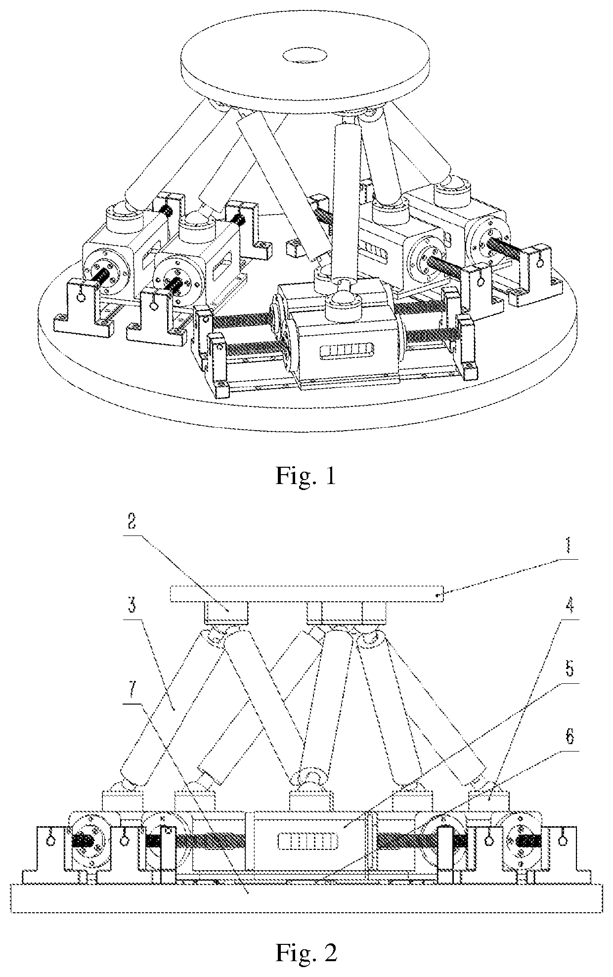
The patent describes a system that can adjust the stiffness of each joint by changing the stiffness of springs, number of permanent magnets and coils, and the magnitude of current. The stiffness adjustment units are arranged horizontally on a lower platform, reducing the rotational inertia of each support rod, which improves the adjustment performance of the stiffness. The stiffness of the system can be actively adjusted and kept constant based on requirements. The system can adapt to different load requirements and will maintain the constant stiffness under different load conditions and the posture of the upper platform. The system has a six-degrees-of-freedom in space, which further improves the adaptability to complex vibration sources.

Problems solved by technology

In the same mechanical device, changes in the position or attitude of the mechanism often result in changes in stiffness of the system during operation.
And changes in stiffness may cause the bearing capacity of the system to decrease, or even change the natural frequency of the system to cause resonance.

Method used


Image

  • Horizontally arranged six-degree-of-freedom constant-stiffness mechanism
  • Horizontally arranged six-degree-of-freedom constant-stiffness mechanism
  • Horizontally arranged six-degree-of-freedom constant-stiffness mechanism

Examples


Embodiment Construction

[0039]The technical solutions in the embodiments of the present disclosure will be clearly and completely described below in conjunction with the accompanying drawings in the embodiments of the present disclosure. Obviously, the described embodiments are only a part of the embodiments of the present disclosure, rather than all the embodiments. Based on the embodiments of the present disclosure, all other embodiments obtained by those of ordinary skill in the art without creative work shall fall within the protection scope of the present disclosure.

[0040]The purpose of the present invention is to provide a horizontally arranged six-degree-of-freedom constant-stiffness mechanism to solve the above-mentioned problems in the prior art. When the attitude or external load of the system changes, the stiffness of the system can be kept constant by controlling current.

[0041]In order to make the above objectives, features and advantages of the present disclosure more obvious and understandabl...


PUM


Abstract

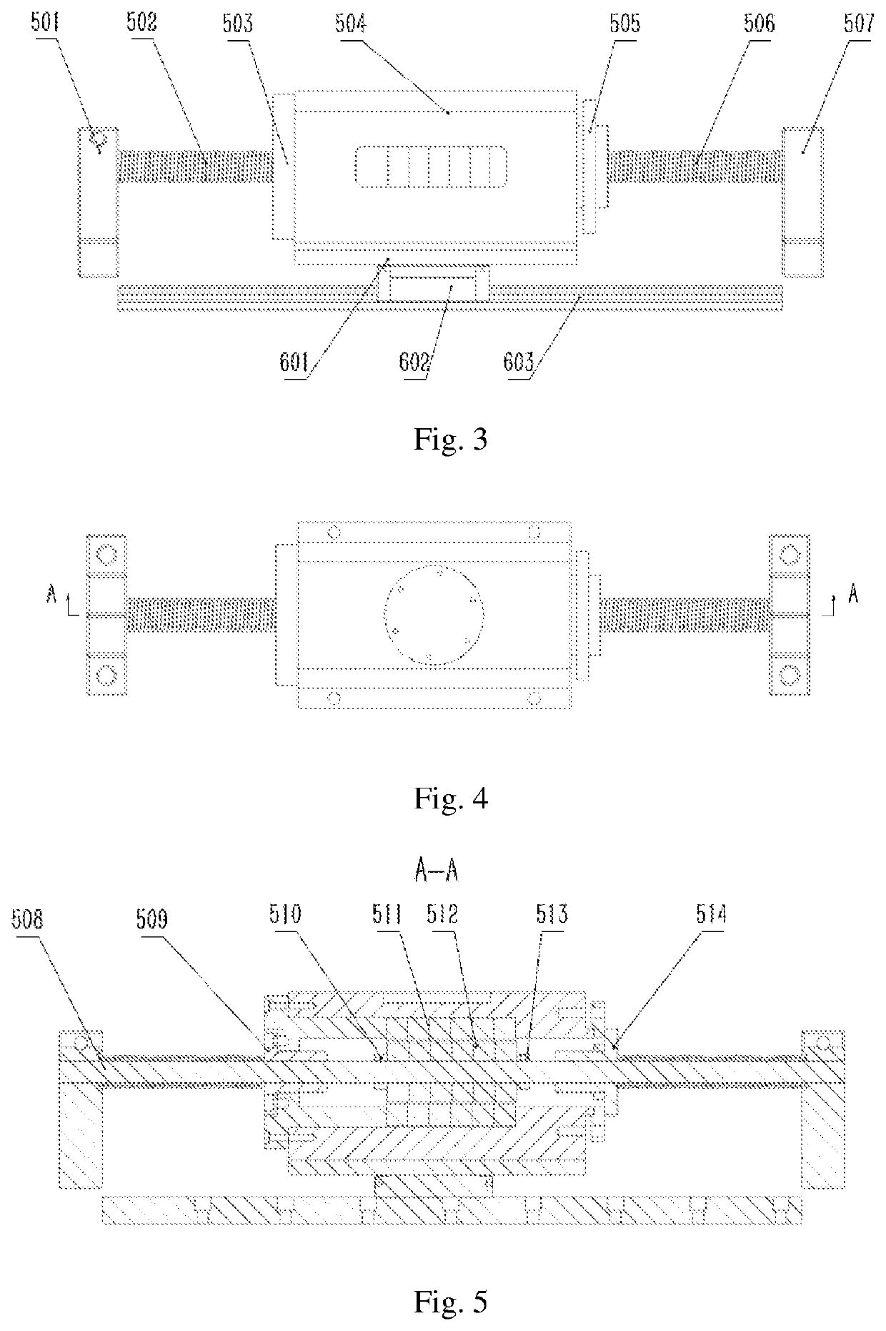
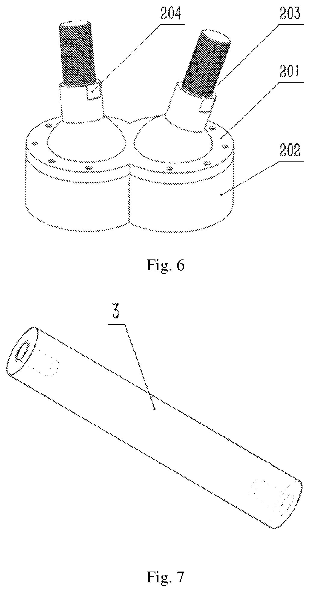
A horizontally arranged six-degree-of-freedom constant-stiffness mechanism is provided, and includes an upper platform, a bottom plate, three composite spherical hinges, spherical hinges, support rods, guide rail slider assemblies, and six electromagnetic adjustable stiffness units. Two ends of a shaft on which a permanent magnet is fixed in each electromagnetic adjustable stiffness unit are fixed to the bottom plate via shaft supports. Axially moving housings of electromagnetic adjustable stiffness units are fixed on sliders of the guide rail slider assemblies via slider backing plates respectively. Guide rail slider assembles are fixed on the bottom plate. Tops of the housings are mounted with the spherical hinges respectively. A bottom of the upper platform is uniformly mounted with the composite spherical hinges. One end of each support rod is threadedly connected to a corresponding one of the spherical hinges, and another end is connected with a corresponding one of composite spherical hinges.

Description

CROSS REFERENCE TO RELATED APPLICATION[0001]This patent application claims the benefit and priority of Chinese Patent Application No. 202110123994.6, titled “HORIZONTALLY ARRANGED SIX-DEGREE-OF-FREEDOM CONSTANT-STIFFNESS MECHANISM”, filed on Jan. 29, 2021, the disclosure of which is incorporated by reference herein in its entirety.TECHNICAL FIELD[0002]The disclosure relates to the technical field of vibration isolation systems, and in particular to a horizontally arranged six-degree-of-freedom constant-stiffness mechanism.BACKGROUND ART[0003]In current industrial design, it have been shown by many design standards and experiences that factors such as stiffness, bearing capacity and sensitivity of a mechanism of the mechanical device, to a large extent, determine function and service life of the mechanical device. The stiffness of the mechanism, as an inherent property of the mechanical system, indicates the bearing capacity and an external-interference-resisting ability of the syste...

Claims


Application Information

Patent Timeline
IPC IPC(8): F16F15/03F16F15/04
CPCF16F15/03F16F15/04F16F2222/06F16F2228/066F16F2228/063F16M11/2078F16F15/02F16F2228/06
Inventor PU, HUAYANWANG, TONGLI, QIMINZHAO, JINGLEILUO, JUNMA, JIE
Owner CHONGQING UNIV
Learn More