Opening/closing chuck and method of manufacturing fingers

a technology which is applied in the field of opening/closing chuck and manufacturing method of fingers, can solve the problems of insufficient development of the technique that takes into account the concentration of stress generated in the fingers and the body, and the damage of the fingers and the sliding surfaces of the body, so as to reduce the concentration of stress and alleviate the concentration of stress

Pending Publication Date: 2022-08-18
SMC CORP
View PDF14 Cites 0 Cited by
  • Summary
  • Abstract
  • Description
  • Claims
  • Application Information

AI Technical Summary

Benefits of technology

[0012]According to the first method of manufacturing and the second method of manufacturing described above, the crowning process for alleviating the concentration of stress generated in the fingers and the body can be easily performed in a fewer number of steps. The above-described concentration of stress is caused by loads acting on the fingers in the vertical direction and moments about the three axes.
[0013]In the opening / closing chuck according to the present invention, crowning is applied to the intersections of the five surfaces including the upper surfaces, the side surfaces, the lower surfaces, the first end surfaces, and the second end surfaces that make up the outer peripheral surfaces of the overhanging portions of the fingers. Therefore, it is possible to alleviate concentration of stress when moments about the three axes or loads in a vertical direction act on the fingers.
[0014]Further, in the first method of manufacturing the fingers according to the present invention, grinding with respect to the side surfaces of the overhanging portions by the first machining tool, and grinding with respect to the upper surfaces and the lower surfaces of the overhanging portions by the second machining tool are combined. Consequently, since crowning is applied to the intersections of the five surfaces of the overhanging portions, the crowning process can be easily performed in a fewer number of steps.
[0015]Further, in the second method of manufacturing the fingers according to the present invention, using a single machining tool, grinding is performed with respect to the side surfaces of the overhanging portions and simultaneously grinding is performed with respect to the upper surfaces and the lower surfaces of the overhanging portions. Consequently, since crowning is applied to the intersections of the five surfaces of the overhanging portions, the crowning process can be easily performed in an even fewer number of steps.

Problems solved by technology

When such loads or moments acting on the fingers are large, concentration of stress occurs on contact surfaces between the fingers and the body, excessive surface pressure is generated, and the fingers and the sliding surfaces of the body are damaged.
However, a technique that takes into consideration concentration of stress generated in the fingers and the body has not yet been sufficiently developed.
However, the disclosed technique does not take into consideration that various three-dimensional axial moments act on the slides.

Method used


Image

  • Opening/closing chuck and method of manufacturing fingers
  • Opening/closing chuck and method of manufacturing fingers
  • Opening/closing chuck and method of manufacturing fingers

Examples


first embodiment

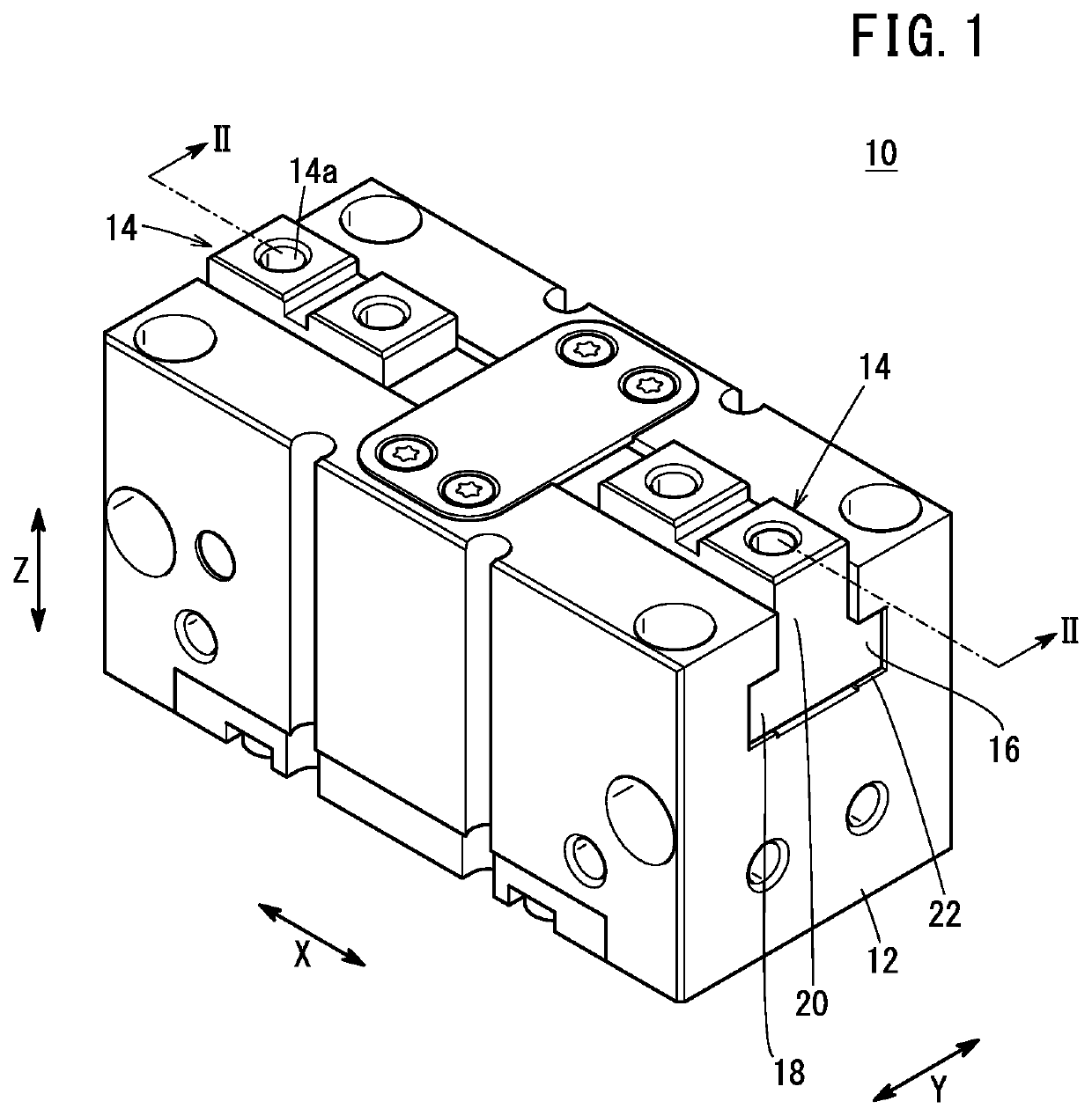
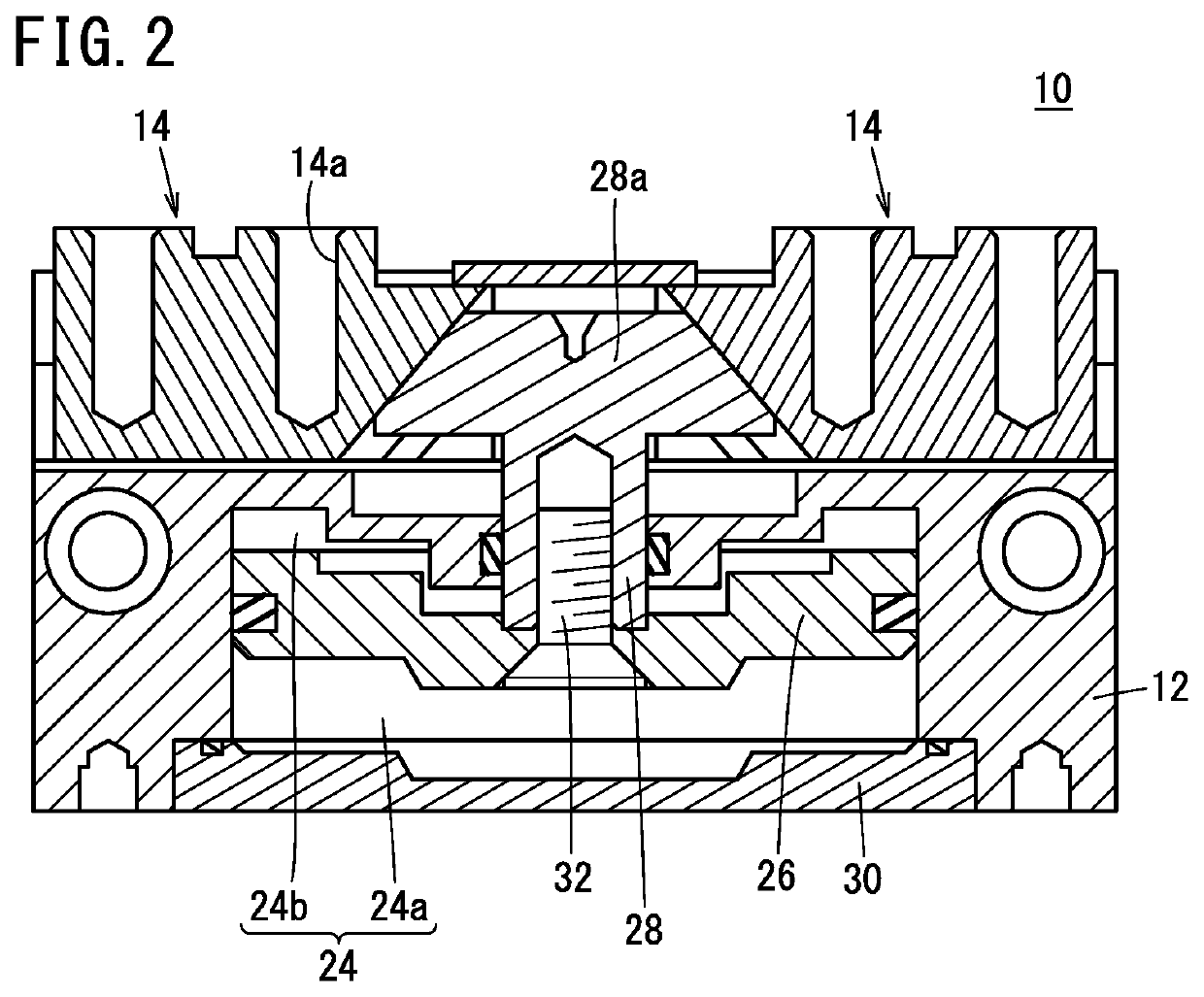
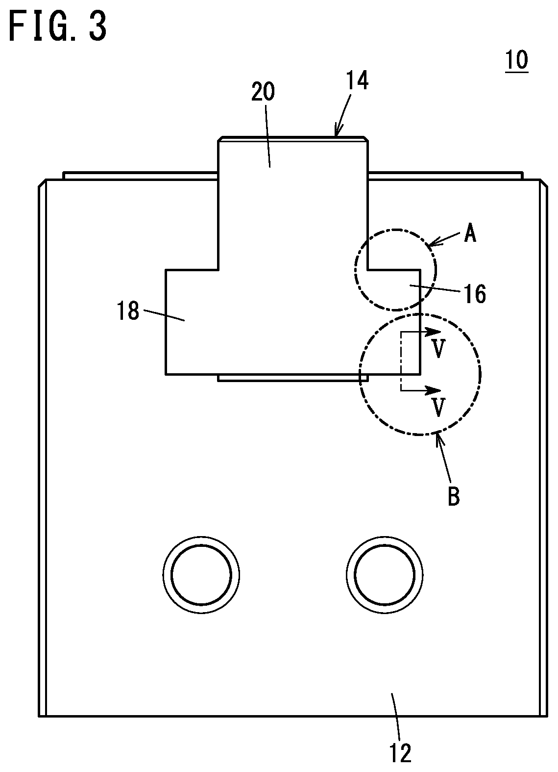
[0035]A description will be given with reference to FIGS. 1 to 6 concerning an opening / closing chuck 10 according to the first embodiment of the present invention. As shown in FIGS. 1 and 2, the opening / closing chuck 10 includes a rectangular parallelepiped shaped body 12, and a pair of fingers 14 that are slidably supported in a longitudinal direction (the X direction) of the body 12. The opening / closing chuck 10 is used by connecting non-illustrated attachments for gripping a workpiece to the fingers 14. That which is shown by reference numeral 14a are screw holes used for connecting the attachments.

[0036]The body 12 includes a cylinder chamber 24 at a lower central part in the longitudinal direction. Further, the body 12 has a guide groove 22 that extends in the longitudinal direction of the body 12, and both ends of which open on end surfaces of the body 12 at portions above the cylinder chamber 24. A piston 26 which is capable of sliding in a vertical direction (Z direction) is...

second embodiment

[0070]Next, a description will be given with reference to FIGS. 10 to 13 concerning a method of manufacturing an opening / closing chuck 40 and fingers 42 thereof according to a second embodiment of the present invention. In the opening / closing chuck 40 according to the second embodiment, the shape of the pair of overhanging portions of the fingers and the shape of the guide groove of the body differ from those of the opening / closing chuck 10 according to the first embodiment.

[0071]As shown in FIGS. 10 and 12, each of the fingers 42 includes a pair of trapezoidal overhanging portions 44 and 46 which project out laterally from a main body portion 48 over the entire length thereof in the longitudinal direction. Upper surfaces 44a and 46a and lower surfaces 44c and 46c of each of the overhanging portions 44 and 46 are formed as tapered surfaces, which are inclined so as to come into closer proximity to each other toward side surfaces 44b and 46b. A guide groove 50 of the body 12 includes...

third embodiment

[0086]Next, a description will be given with reference to FIGS. 14 and 15 concerning fingers 62 of an opening / closing chuck and a method of manufacturing the same according to a third embodiment of the present invention. The fingers 62 according to the third embodiment differ from the fingers 42 of the opening / closing chuck according to the second embodiment, in that each of the overhanging portions includes a recess and a grease reservoir.

[0087]As shown in FIG. 14, one of the overhanging portions 64 includes a recess 72 centrally in the longitudinal direction of the upper surface 64a, the side surface 64b, and the lower surface 64c, and includes crowning regions CR1 and CR2 at both ends of the recess 72. A grease reservoir 70 opens in a bottom surface of the recess 72 that is formed in the upper surface 64a. The other one of the overhanging portions 66 also includes a similar grease reservoir 70 therein. Grease that is stored in the grease reservoirs 70 is supplied to the sliding s...


PUM

PropertyMeasurementUnit
reaction forceaaaaaaaaaa
gripping forceaaaaaaaaaa
distanceaaaaaaaaaa

Abstract

A finger includes a pair of overhanging portions that project out laterally from a main body portion. Outer peripheral surfaces of the overhanging portions are made up from five surfaces including upper surfaces, side surfaces, lower surfaces, first end surfaces, and second end surfaces. Crowning is applied to the intersections between these surfaces.

Description

CROSS-REFERENCE TO RELATED APPLICATIONS[0001]This application is based upon and claims the benefit of priority from Japanese Patent Application No. 2021-023916 filed on Feb. 18, 2021, the contents of which are incorporated herein by reference.BACKGROUND OF THE INVENTIONField of the Invention[0002]The present invention relates to an opening / closing chuck equipped with a pair of fingers for gripping a workpiece, as well as a method for manufacturing the fingers.Description of the Related Art[0003]Conventionally, an opening / closing chuck has been known in which a pair of fingers for gripping a workpiece are slidably supported in directions to approach and separate away from each other. For example, in JP 2003-526528 A, a parallel gripper is disclosed which adjusts a wedge-shaped hook transmission portion by a piston. The wedge-shaped hook transmission portion brings two base jaws, which are movably guided in a housing, into closer proximity or farther away from each other.[0004]Further...

Claims


Application Information

Patent Timeline
Patent Type & Authority Applications(United States)
IPC IPC(8): B23B31/19
CPCB23B31/19B23B31/02B23B31/103B23B31/30B24B19/00B24B7/16B24B9/00B24B27/0076B23B31/16237B23B31/16254B23B2270/027B25J15/028B23B2231/24B25J19/0062B23B2231/32B24B19/009B24B27/003B24B15/00B25J15/0253B25J19/007
Inventor SATO, MOTOHIRO
Owner SMC CORP
Why Eureka
Try Eureka