
Cleaning unit having agitator

Active Publication Date: 2022-08-25
LG ELECTRONICS INC
View PDF5 Cites 0 Cited by
  • Summary
  • Abstract
  • Description
  • Claims
  • Application Information

AI Technical Summary

Benefits of technology

The present invention relates to a cleaner that can adjust the rotation radius of its brush based on the floor environment, making it easier to clean different surfaces. The user can easily change the brush rotation without touching dust, ensuring a cleaning performance regardless of the floor. The cleaner can also have a bearing between the shaft and the agitator, allowing the brush to extend or reduce its rotation radius. Additionally, a fixed brush may be added to always apply a suitable pressure to the surface. The brush may also have two inclined brushes with different lengths, ensuring a constant pressure on the surface.

Problems solved by technology

However, when the floor environment is a carpet environment, since the suction nozzle module is spaced apart from a surface of the carpet, the brush or rubber plate of the agitator does not reach the surface of the carpet, thereby decreasing cleaning performance.
However, for this purpose, a user has to separate the brush from the existing groove and assemble it into another groove whenever the floor environment changes, there is a sanitary problem in that the user has to touch dust accumulated in the agitator with his or her hand, a time loss occurs for replacement, and also there is a problem that cannot be applied to an automatic cleaning device such as a robot cleaner.

Method used


Image

  • Cleaning unit having agitator
  • Cleaning unit having agitator
  • Cleaning unit having agitator

Examples


Embodiment Construction

[0060]First, prior to describing an agitator according to the present disclosure, a cleaner in the related art to which an agitator can be coupled will be described.

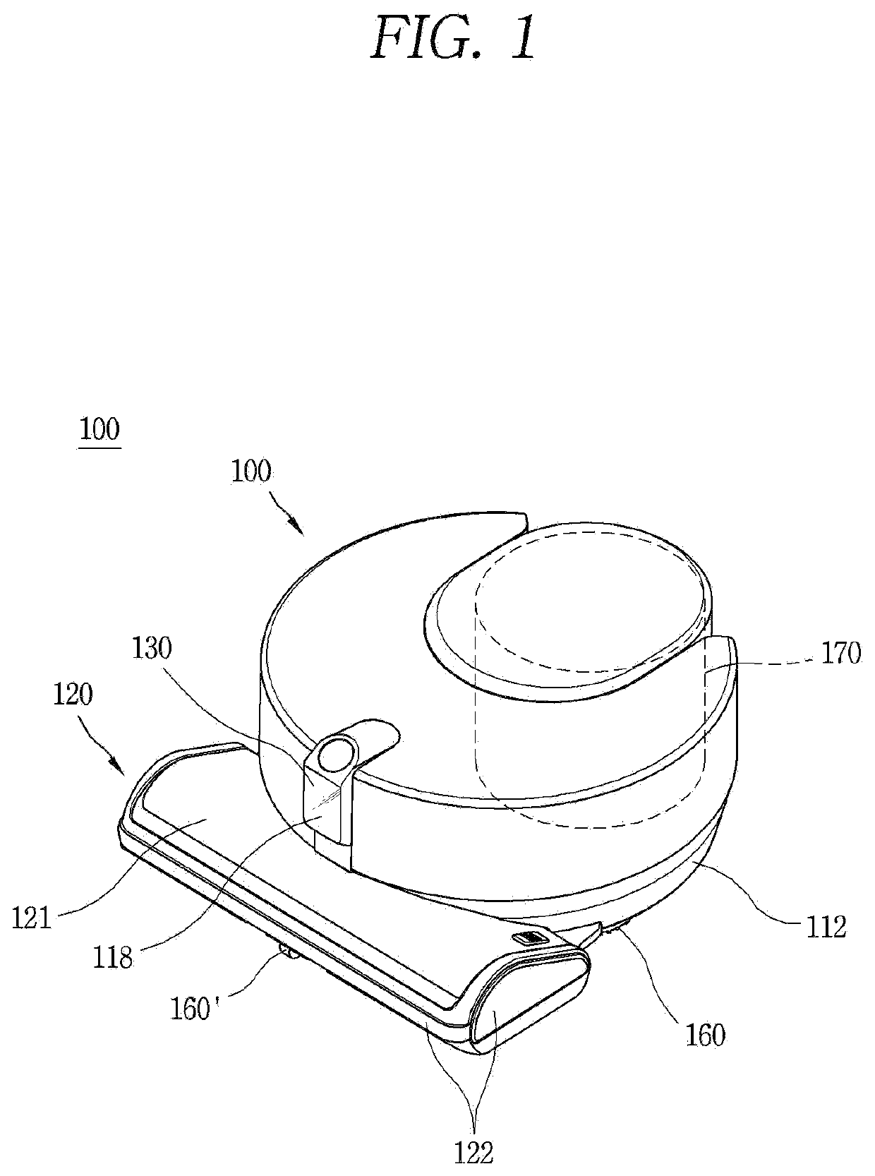
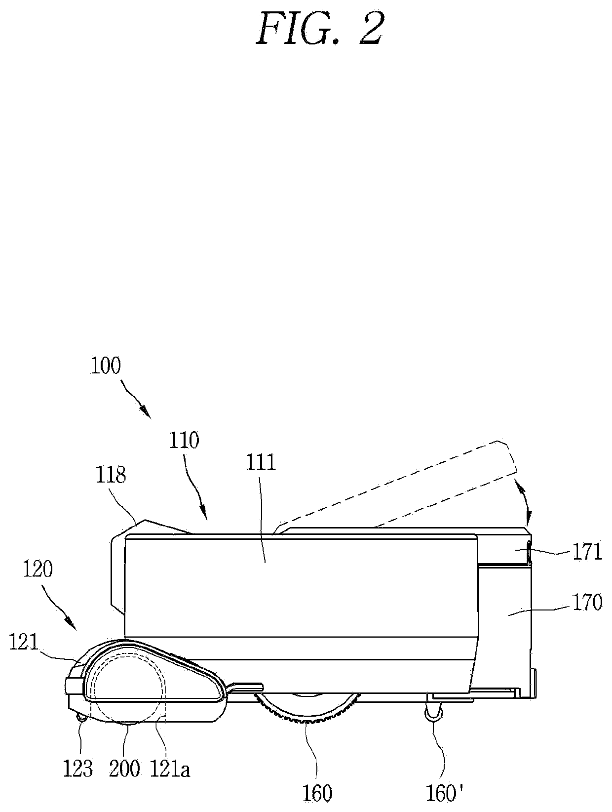
[0061]FIG. 1 is a perspective view illustrating an example of a cleaner in the related art, and FIG. 2 is a side view of the cleaner illustrated in FIG. 1.

[0062]A robot cleaner 100 may be configured to perform a function of mopping a floor as well as a function of sucking dust on the floor. To this end, the robot cleaner 100 includes a cleaner body 110 and a suction nozzle module 120.

[0063]The cleaner body 110 and the suction nozzle module 120 define an exterior of the robot cleaner 100. Various parts including a controller (not shown) for controlling the robot cleaner 100 are embedded or mounted in the robot cleaner 100. Furthermore, various parts for cleaning an area to be cleaned are mounted in the suction nozzle module 120.

[0064]An exterior of the cleaner body 110 is defined by an outer cover 111 and a base body 112....


PUM


Abstract

The present invention provides a cleaning unit, comprising: a columnar body part having a rotation guide opening formed on the outer circumferential surface thereof; a shaft installed to reciprocate a predetermined distance in the longitudinal direction thereof in a hollow formed in the body part; a drive part that protrudes from the shaft in the radial direction thereof; a brush part that has one side installed on the outer circumferential surface of the body part along the longitudinal direction thereof and rotates on the basis of the one side as a rotation axis; and a driven part that extends from the brush part toward the drive part, passes through the rotation guide opening, and is inserted into a rotation guide groove formed in the drive part. The rotation guide groove extends at a predetermined angle with respect to the longitudinal direction of the shaft, and as the shaft reciprocates, the driven part is guided to rotate by means of the rotation guide groove, and the brush is rotated by means of the rotation of the driven part. The cleaning unit may include a robot cleaner or a cleaner operated by means of a user's operation.

Description

TECHNICAL FIELD[0001]The present disclosure relates to a cleaning unit, and more particularly, to a cleaning unit having an agitator with a rotating brush when a cleaner is operated on a carpet.BACKGROUND ART[0002]A cleaner is a device that performs a vacuum cleaning function by sucking dust and foreign substances together with air and separating them to collect dust. The cleaner includes a suction nozzle module, and the suction nozzle module comes into contact with a surface to be cleaned to suck dust and foreign substances present on the surface together with air. In particular, the cleaner is mainly operated in a floor environment.[0003]The suction nozzle module has an agitator for floating or picking up dust and foreign substances from the surface to be cleaned. A brush or rubber plate protrudes from an outer peripheral surface of a cylindrical body of the agitator, and as the agitator rotates, the brush or rubber plate rotates together to float or pick up dust and foreign subst...

Claims


Application Information

Patent Timeline
IPC IPC(8): A47L9/04A47L9/28A46B9/02A46B13/00A46B13/02
CPCA47L9/0477A47L9/0455A47L9/0411A47L9/2831A47L9/2847A47L9/0483A46B9/026A46B13/001A46B13/02A46B2200/3033A47L2201/06A46B13/005A46B2200/30A47L9/2826A47L9/0494A46B7/026A47L9/0466A47L9/2805
Inventor PARK, JONGHOLEE, SANGIKHONG, WOO
Owner LG ELECTRONICS INC
Features
  • Generate Ideas
  • Intellectual Property
  • Life Sciences
  • Materials
  • Tech Scout
  • Unparalleled Data Quality
  • Higher Quality Content
  • 60% Fewer Hallucinations
Learn More