Electric machine assembly having a wire guiding structure

Pending Publication Date: 2022-08-25
REGAL BELOIT AMERICA
View PDF0 Cites 0 Cited by
  • Summary
  • Abstract
  • Description
  • Claims
  • Application Information

AI Technical Summary

Benefits of technology

The patent describes an electric machine assembly with a mid-frame that separates the inner cavity of the housing into two compartments. The mid-frame has a guide structure to guide wires from the stator to the electrical component, preventing contact between the wires and the rotating member. This design results in a more efficient and reliable electric machine assembly.

Problems solved by technology

Further, at least some known electrical machine assemblies include components where contact between these components and the excess wiring is undesirable.

Method used


Image

  • Electric machine assembly having a wire guiding structure
  • Electric machine assembly having a wire guiding structure
  • Electric machine assembly having a wire guiding structure

Examples


Embodiment Construction

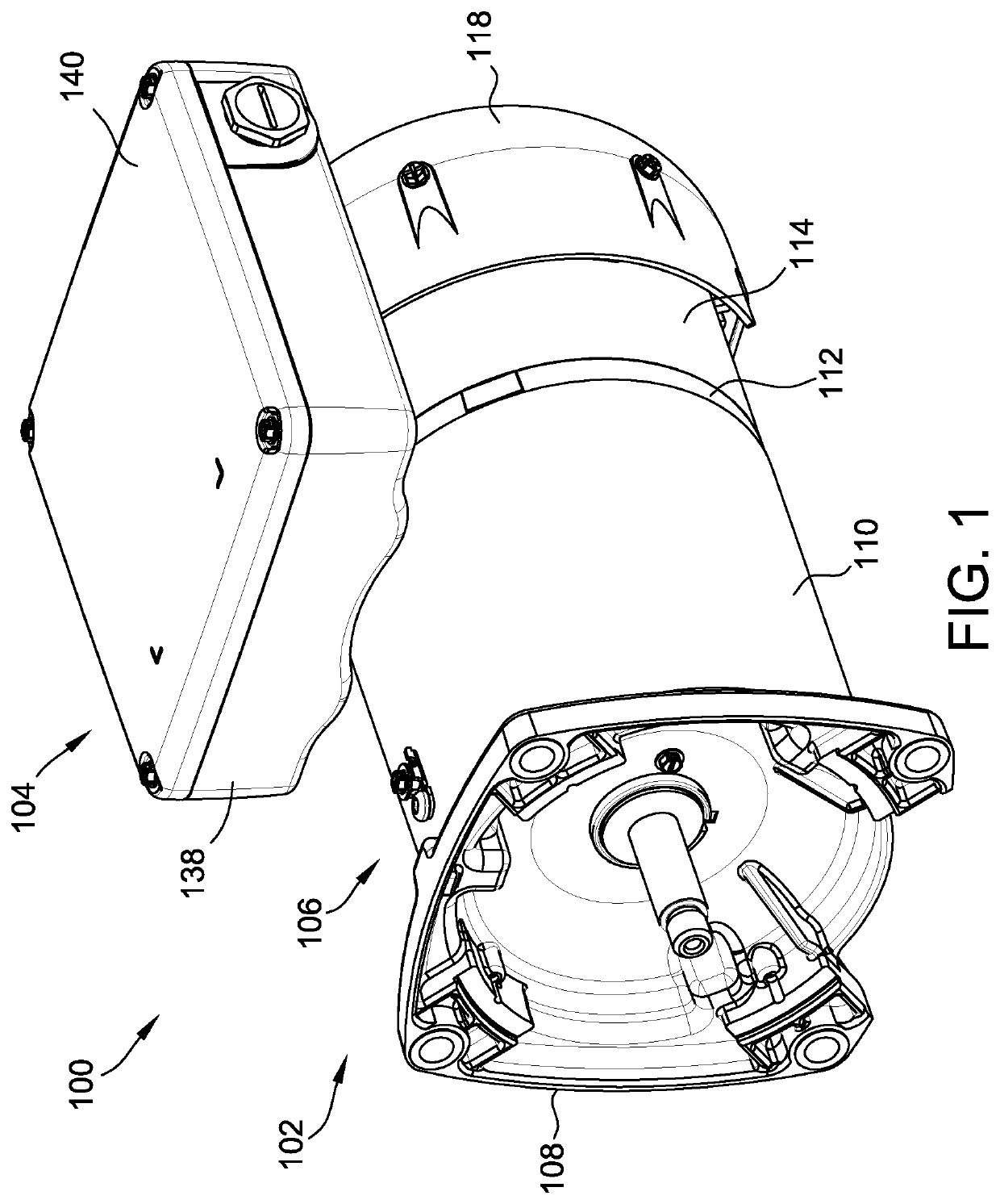
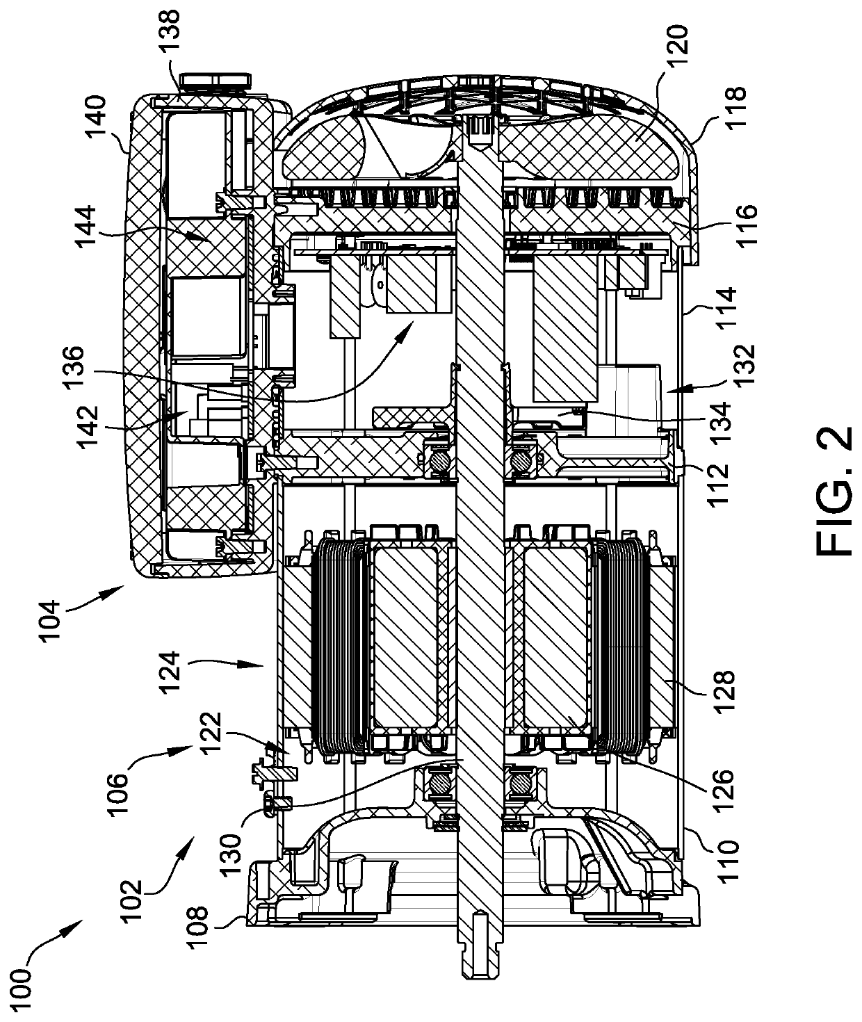
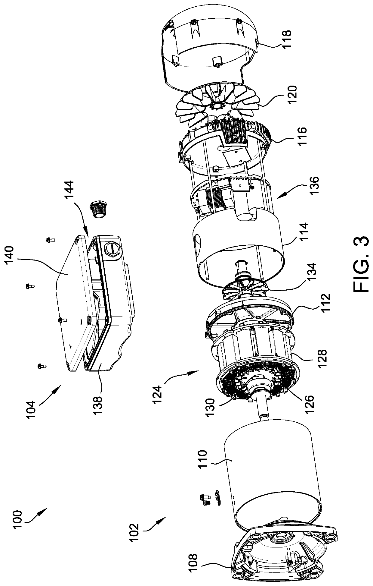
[0038]FIG. 1 is a perspective view of an exemplary electric machine assembly 100; FIG. 2 is a cross-sectional view of electric machine assembly 100; and FIG. 3 is a partially exploded view of electric machine assembly 100.

[0039]In the exemplary embodiment, electrical machine assembly 100 includes a motor assembly 100 coupled to a terminal box 104. In some embodiments, the terminal box 104 is removably coupled to the housing 106. In some embodiments, the housing 106 comprises a first plurality of housing openings and a second plurality of housing openings. Motor assembly 100 includes a housing 106 that includes a mounting bracket 108, a first housing portion 110 coupled to mounting bracket 108, a mid-frame 112 coupled to first housing portion 110, a second housing portion 114 coupled to mid-frame 112 opposite first housing portion 110, an end frame 116 coupled to second housing portion 114, and a shroud 118 coupled to second housing portion 114. The housing 106 defines an inner cavit...


PUM


Abstract

An electric machine assembly includes a housing defining an inner cavity and an electrical component positioned within the cavity. The electric machine assembly also includes a mid-frame positioned within the cavity and configured to separate the cavity into a first compartment and a second compartment. The mid-frame includes a guide structure for guiding a plurality of wires through the second compartment toward the electrical component.

Description

[0001]This application claims priority to U.S. Provisional Application No. 63 / 153,660, filed Feb. 25, 2021, which is hereby incorporated by reference in its entirety.BACKGROUND[0002]The field of the invention relates generally to electrical machine assemblies and, more particularly, to safely channeling wiring through the electrical machine assemblies.[0003]At least some known electrical machine assemblies include internal wiring that extends through the interior of the assembly between electrically connected components. During assembly, it is advantageous for there to be sufficient slack in the wiring to allow for electrical coupling. Such slack may congregate within a cavity of the housing. Further, at least some known electrical machine assemblies include components where contact between these components and the excess wiring is undesirable.BRIEF DESCRIPTION[0004]In one aspect, an electric machine assembly is provided. The electric machine assembly includes a housing defining an ...

Claims


Application Information

Patent Timeline
IPC IPC(8): H02K5/22H02G11/00H05K7/14
CPCH02K5/225H02G11/00H05K7/1491H02K11/33H02K9/14H02K5/18H02K2213/09H02K1/30H02K9/08H02K2205/09H02K1/2773H02K5/10H02K15/02H02K5/15H02K9/06H02K9/227H02K3/522H02K2203/06
Inventor CROSSON, JEFFREY WILLIAM
Owner REGAL BELOIT AMERICA
Why Eureka
Try Eureka