
Flat strain wave gearing

a gearing and strain wave technology, applied in the direction of gearing elements, cams, gearing, etc., can solve problems such as difficulty in flattening, and achieve the effect of improving the torque transmission characteristics of the second teeth and the rigidity with which the flexible gear is supported by the wave generator

Pending Publication Date: 2022-09-15
HARMONIC DRIVE SYST IND CO LTD
View PDF10 Cites 0 Cited by
  • Summary
  • Abstract
  • Description
  • Claims
  • Application Information

AI Technical Summary

Benefits of technology

The present invention is a flat strain wave gearing that can flex in the axial direction. The gear is formed in a flat conical shape with curved teeth that are connected to a rigid boss through a flexible diaphragm. The second teeth are supported from the axial direction, which improves torque transmission and ensures a high level of rigidity. The tooth formation portion can flex easily to ensure proper meshing with the first teeth. The technical effect of this invention is a more efficient and effective gear system that can provide high-speed, low-torque, or high-torque output.

Problems solved by technology

Specifically, the axial length is determined according to the tooth width of the flexible gear and the lengths of a barrel part and a diaphragm of the flexible gear, and is difficult to flatten.

Method used


Image

  • Flat strain wave gearing
  • Flat strain wave gearing
  • Flat strain wave gearing

Examples


Embodiment Construction

[0022]An embodiment of a flat strain wave gearing to which the present invention is applied is described below with reference to the accompanying drawings.

(Flat Strain Wave Gearing)

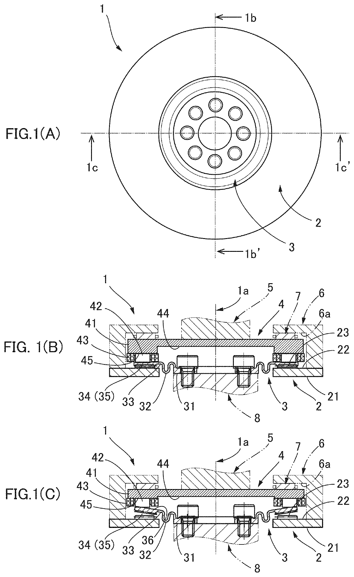
[0023]FIG. 1(A) is a schematic end-surface view of a flat strain wave gearing according to an embodiment of the present invention, FIG. 1(B) is a schematic longitudinal cross-sectional view showing a portion sectioned at a line 1b-1b′ of FIG. 1(A) and FIG. 1(C) is a schematic longitudinal cross-sectional view showing a portion sectioned at a line 1c-1c′ of FIG. 1(A). The flat strain wave gearing 1 is provided with a rigid gear 2, a flexible gear 3 that is formed to have a flat truncated-cone shape, and a wave generator 4. The wave generator 4 causes the flexible gear 3 to flex in the direction of a central axis 1a (axial direction) and mesh with the rigid gear 2 at a plurality of positions that are set apart in the circumferential direction.

[0024]The rigid gear 2 is provided with an annular member 21 of u...


PUM


Abstract

The flat strain wave gearing is provided with an axially arranged rigid gear, flexible gear and wave generator. The flexible gear forms a flat truncated cone shape, has a tooth formation portion connected via a bellows-shaped cross-sectional diaphragm to a rigid boss which is an output shaft linking part. The flat strain wave gearing can ensure axial flexibility of the tooth formation portion, and can enable teeth of the flexible gear to mesh favorably with teeth of the rigid gear in the axial direction in each position in the tooth trace direction. Local bias of the load torque in the meshing portion in the tooth formation portion can also be suppressed.

Description

TECHNICAL FIELD[0001]The present invention relates to a strain wave gearing, and in particular relates to a flat strain wave gearing that has a short axial length and that is configured such that a flexible gear facing a rigid gear in the axial direction is caused to flex in the axial direction and partially mesh with the rigid gear.BACKGROUND ART[0002]In strain wave gearings having a “cup” profile, which are the mainstream form of strain wave gearings, a flexible gear having external teeth that are parallel to the axial direction is flexed in an ellipsoidal shape by a wave generator. The flexible gear that has been flexed in the ellipsoidal shape meshes with internal teeth of a rigid gear that is disposed on the radially outer side thereof at locations on and near the long axis of the ellipsoidal shape in a state of meshing that is substantially parallel to the axial direction. Strain wave gearings having a “cup” profile are superior to those having a “pancake” profile (strain wave...

Claims


Application Information

Patent Timeline
Patent Type & Authority Applications(United States)
IPC IPC(8): F16H49/00F16H53/02
CPCF16H49/001F16H53/02F16H55/0833F16H2049/003F16H1/32F16H55/10F16H53/025
Inventor KOBAYASHI, MASARU
Owner HARMONIC DRIVE SYST IND CO LTD
Features
  • Generate Ideas
  • Intellectual Property
  • Life Sciences
  • Materials
  • Tech Scout
  • Unparalleled Data Quality
  • Higher Quality Content
  • 60% Fewer Hallucinations
Learn More