Supercharge Your Innovation With Domain-Expert AI Agents!

Vertical Motion Mixing Drive

a technology of vertical motion and mixing unit, which is applied in the direction of mixing, transportation and packaging, biological water/sewage treatment, etc., can solve the problems of affecting the final assembly, affecting the efficiency of mixing, and requiring a great deal of fabrication and maintenance, so as to reduce the chance of misalignment in the final assembly

Pending Publication Date: 2022-09-22
OVIVO INC
View PDF6 Cites 0 Cited by
  • Summary
  • Abstract
  • Description
  • Claims
  • Application Information

AI Technical Summary

Benefits of technology

The invention simplifies a mixing assembly by reducing moving parts and minimizing lubrication requirements. It avoids the use of fixed guide rails and yokes that move up and down, which reduces wear and tear. Overall, the invention creates a more durable and reliable mixing assembly.

Problems solved by technology

Conventional mixing drives for this purpose have not been optimized for mixing efficiency and maintenance requirements.
Typical vertical motion mixer drive units have many moving parts and require a great deal of fabrication and maintenance.
The driving mechanisms of the mixing units are subjected to considerable wear, particularly in gearing and other moving parts, due to the repeated reversal of direction of the mixing disc, which induces considerable wear in gearing and other components handling rotational and translational movement.

Method used


Image

  • Vertical Motion Mixing Drive
  • Vertical Motion Mixing Drive
  • Vertical Motion Mixing Drive

Examples


Embodiment Construction

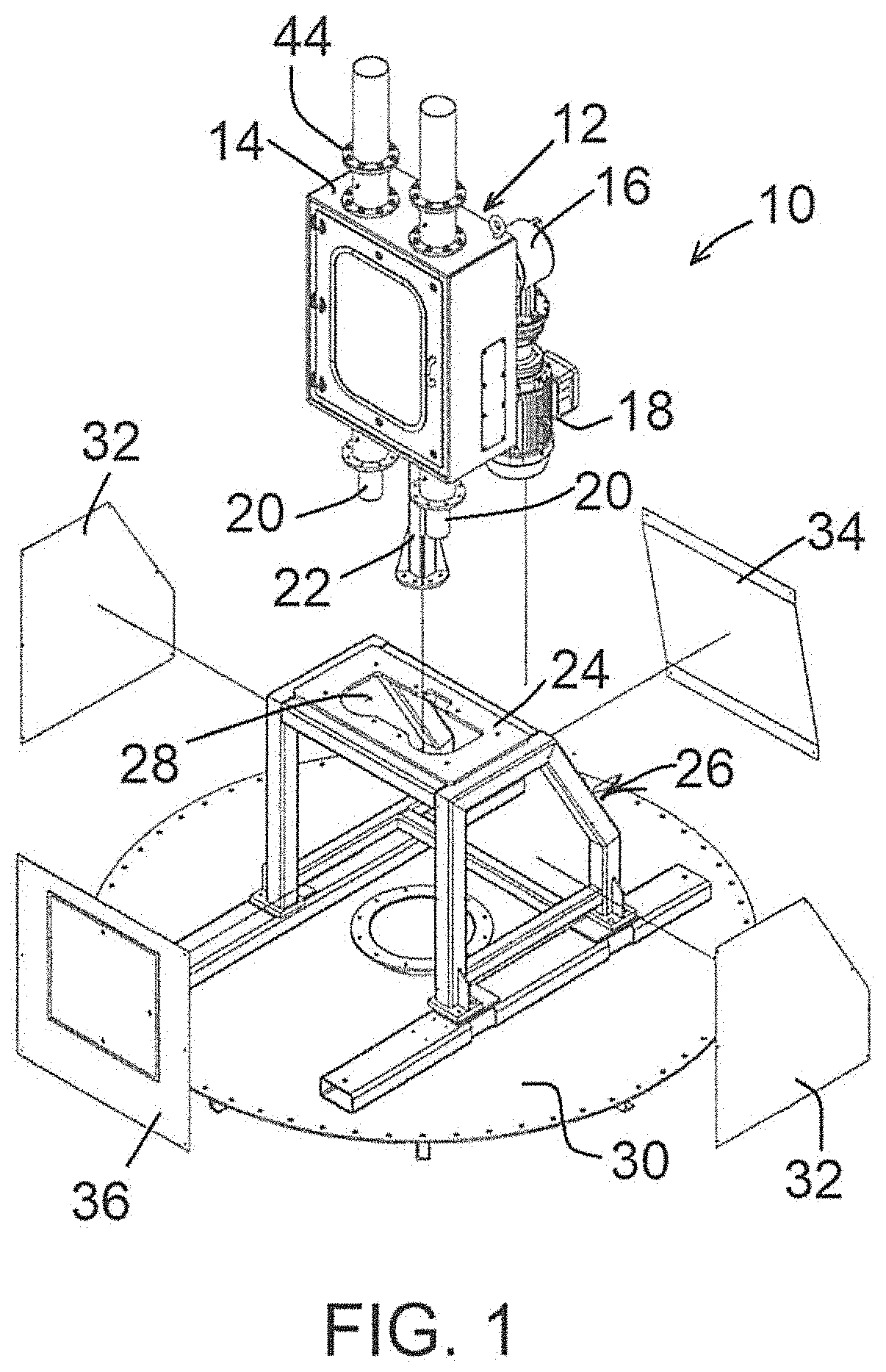
[0024]In FIG. 1 an assembly 10 is shown, exploded in this view, for a vertical motion drive mechanism which can be secured on a tank containing liquids or slurry to be mixed. In this view the drive mechanism 12 itself is shown with a housing 14, and at the rear of the housing a drive gearing / crank assembly 16 driven by a motor 18. Guide rods or shafts are shown at 20, at left and right of the unit, these rods being movable relative to the housing. A mixer shaft is shown at 22, extending down out of the housing, connected into the driving mechanism. When components are assembled into an assembled structure 10, the housing 14 is seated on an upper surface 24 of a support frame 26, an opening 28 being shown for the movable rods 20 and the mixer shaft 22. The support frame 26 rests on a surface 30, which can be a plate as shown, or which can be the top surface of a tank, such as an anaerobic digester tank in a sewage treatment facility. For this purpose the plunger shaft 22 is extended ...


PUM


Abstract

A vertical motion mixer has a drive mechanism with two axes of guidance for vertical motion. A reciprocating yoke is fixedly secured to the driving shaft for the mixer, without any guide bearing for the mixer driving shaft. The mixer drive unit is of compact and simplified design with minimal moving parts, and including drive gearing with planetary gears to minimize wear during reciprocating movement.

Description

BACKGROUND OF THE INVENTION[0001]The invention concerns vertical motion mixers, which may be used in wastewater treatment systems or for other purposes. More particularly the invention encompasses an improved vertical motion drive mechanism for driving a mixing disc in reciprocal motion for mixing of liquids or slurries.[0002]In sewage treatment plants, particularly in anaerobic digestion, reciprocating motion mixers are often used, positioned within a liquid / slurry-filled tank so as to drive a mixing disc up and down in reciprocating motion. Typically the stroke of the disc is about 12 to 20 inches. See, for example, prior U.S. Pat. Nos. 10,611,654, 9,162,195, 7,685,896, 7,399,112 and 6,830,369.[0003]Conventional mixing drives for this purpose have not been optimized for mixing efficiency and maintenance requirements. Typical vertical motion mixer drive units have many moving parts and require a great deal of fabrication and maintenance. The driving mechanisms of the mixing units a...

Claims


Application Information

Patent Timeline
Patent Type & Authority Applications(United States)
IPC IPC(8): B01F11/00B01F15/00
CPCB01F11/0097B01F11/0082B01F15/00448B01F15/00467B01F15/00538B01F2015/0011B01F2215/0052B01F31/441C02F3/1284C02F3/2866B01F35/325B01F2035/352B01F2101/305B01F35/3204B01F31/70B01F35/323
Inventor CHRISTIANSEN, HAYDONGOLDHARDT, JAMESHARWOOD, JACOB
Owner OVIVO INC
Features
  • R&D
  • Intellectual Property
  • Life Sciences
  • Materials
  • Tech Scout
  • Unparalleled Data Quality
  • Higher Quality Content
  • 60% Fewer Hallucinations
Learn More