
Sealing plate equipped with gas discharge valve and secondary battery using the same

a technology of secondary batteries and sealing plates, which is applied in the direction of batteries, cell components, vent arrangements, etc., can solve the problems of large processing load, large plastic deformation of metals, and high processing load, and achieve the effect of reducing mass production stability and large metal deformation

Pending Publication Date: 2022-10-06
PRIME PLANET ENERGY & SOLUTIONS INC +1
View PDF0 Cites 0 Cited by
  • Summary
  • Abstract
  • Description
  • Claims
  • Application Information

AI Technical Summary

Benefits of technology

The patent text discusses a sealing plate with a gas discharge valve that reduces processing load and work hardening during molding and excels in mass production stability and freedom of design. Additionally, it provides a secondary battery that is highly reliable and can be easily designed and mass-produced. The technical effect of this invention is to improve the stability and efficiency of gas discharge valves in sealing plates and secondary batteries.

Problems solved by technology

In the molding of such a thin-film portion, a large amount of metal is plastically deformed and the processing load is very large.
The resulting problem is that mass production stability is likely to be lowered due to molding defects.
Further, since the thin-film portion formed by plastically deforming a large amount of metal is subjected to a large work hardening, the thin-film portion may not be broken at a predetermined internal pressure.
Therefore, in the conventional gas discharge valve, it is necessary to design the dimensions of each part so as to operate (open) at a desired pressure in consideration of the degree of work hardening after molding, so that the degree of freedom of design is very limited.
When the gas discharge valve is opened, the protruding portion connected to the base portion via a part of the thin-walled portion may stay in the space in the second direction of the opening, and may hinder the escape of gas from the inside of the battery case.

Method used


Image

  • Sealing plate equipped with gas discharge valve and secondary battery using the same
  • Sealing plate equipped with gas discharge valve and secondary battery using the same
  • Sealing plate equipped with gas discharge valve and secondary battery using the same

Examples


Embodiment Construction

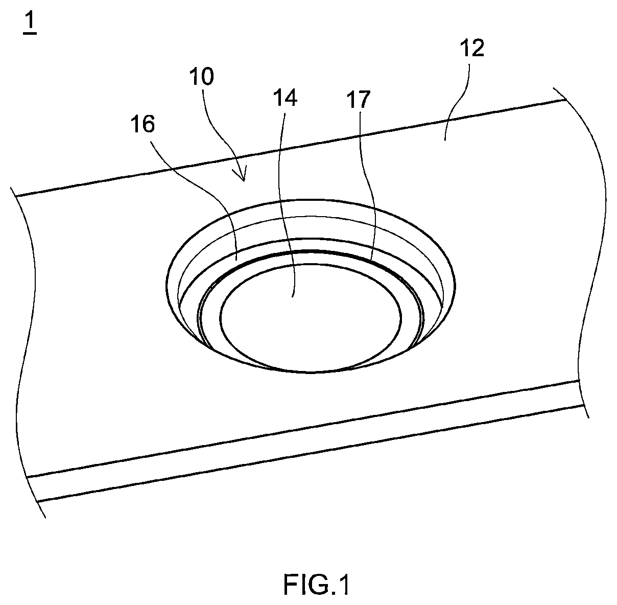
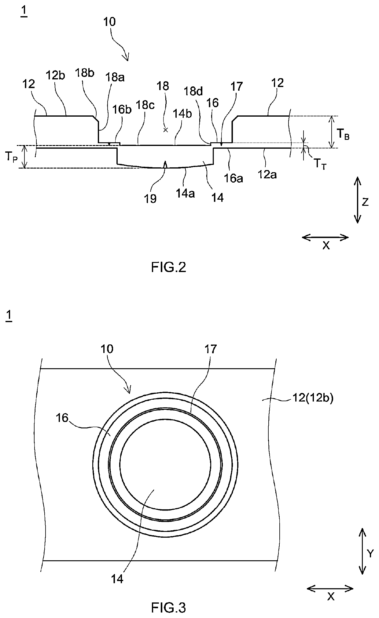
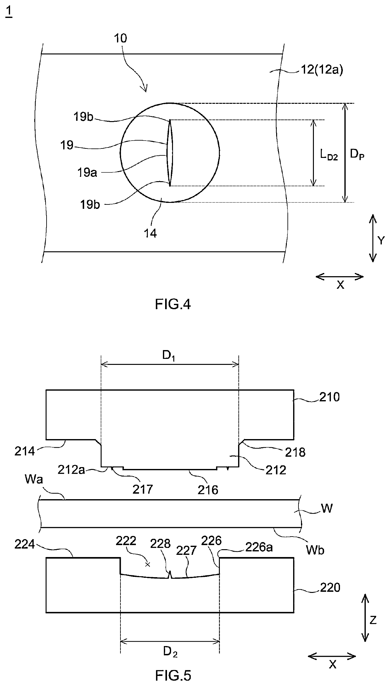
[0038]Hereinafter, some preferred embodiments of the technique disclosed herein will be described with reference to the drawings. It should be noted that matters other than those specifically mentioned in the present description and necessary for carrying out the technique disclosed herein (for example, materials for electrodes and electrolytes) can be ascertained as design matters for a person skilled based on the related art in the pertinent field. That is, the technique disclosed herein can be implemented based on the contents disclosed in the present description and the general technical knowledge in the field.

[0039]In the drawings referred to in the following description, the same reference numerals are given to the members / parts that perform the same action. Furthermore, the dimensional relationships (length, width, thickness, etc.) in each drawing do not reflect the actual dimensional relationships. It is assumed that the reference symbol X in each figure indicates the “width...


PUM


Abstract

According to the present disclosure, there is provided a sealing plate equipped with a gas discharge valve that reduces processing load and work hardening during molding. A gas discharge valve of a sealing plate 1 disclosed herein has a flat plate-shaped base portion and a protruding portion protruding from a first surface of the base portion in a first direction, an annular thin-walled portion having a thickness smaller than the thickness of the protruding portion is provided around the protruding portion, and a first surface of the thin-walled portion is substantially on the same surface as the first surface of the base portion. In the gas discharge valve having the above configuration, the total amount of metal that is plastically deformed is reduced by limiting the formation region of the thin-walled portion to the periphery of the protruding portion.

Description

CROSS REFERENCE TO RELATED APPLICATIONS[0001]This application claims priority based on Japanese Patent Application No. 2021-060890 filed on Mar. 31, 2021, and the entire contents of the application are incorporated herein by reference.BACKGROUND1. Technical Field[0002]The present disclosure relates to a sealing plate equipped with a gas discharge valve and a secondary battery using the same.2. Description of the Related Art[0003]A secondary battery such as a lithium ion secondary battery includes, for example, an electrode body and a battery case that accommodates the electrode body. The battery case includes an exterior body that is a container having an opening on one side, and a sealing plate that closes the opening of the exterior body. In this type of secondary battery, a gas discharge valve may be provided in the battery case (typically, a sealing plate) to improve safety. This gas discharge valve is a secondary battery component including a valve designed to open at a predete...

Claims


Application Information

Patent Timeline
IPC IPC(8): H01M50/342
CPCH01M50/3425H01M2200/20H01M50/184H01M50/30H01M10/0525H01M50/103H01M50/15H01M50/342Y02E60/10
Inventor MARUBAYASHI, HIRONORIWAKIMOTO, RYOICHIYONEYAMA, AKIHIROFUJII, AKIRAODAGAKI, TOSHIHIROKAWAI, KATSUHISA
Owner PRIME PLANET ENERGY & SOLUTIONS INC
Learn More