Preferential visual acuity test cabin

a visual acuity and test cabin technology, applied in the field of preferred visual acuity test cabins, can solve the problems of inability of the card, difficult for the professional to reach a precise diagnosis in respect of the preferred visual acuity test, etc., and achieve the effect of improving accuracy and better visualization of the card

Pending Publication Date: 2022-10-13
RASSI GABRIEL LUIS ALEXANDRE
View PDF0 Cites 0 Cited by
  • Summary
  • Abstract
  • Description
  • Claims
  • Application Information

AI Technical Summary

Benefits of technology

The invention is a booth designed for a preferred visual acuity test using Teller cards. The booth provides a safe and isolated environment for the patient, reducing external distractions and ensuring a precise diagnosis of patient's actions. The booth also features fixed and controlled lighting to improve visualization of the card during the test. The use of the booth significantly increases the accuracy, reliability, and reproductivity of the preferred visual acuity tests.

Problems solved by technology

It happens that, in order to perform the test, the professional needs to hold the card with the hands, at the height of patient's eyes, as well it should be positioned in a way that the eye is positioned at the professional's eyes height, which leads to instability of the card.
Another inconvenient bound to the visual acuity method of ‘Teller’ card verification, in the form it is currently applied, refers to the external distractions, for example, the hands of the professional, while he was sustaining the card, so that the patient deviates his look, instead of focusing the set of contracting stripes, thus making it difficult for the professional to reach a precise diagnosis in respect to the preferred visual acuity test.

Method used


Image

  • Preferential visual acuity test cabin
  • Preferential visual acuity test cabin
  • Preferential visual acuity test cabin

Examples


Embodiment Construction

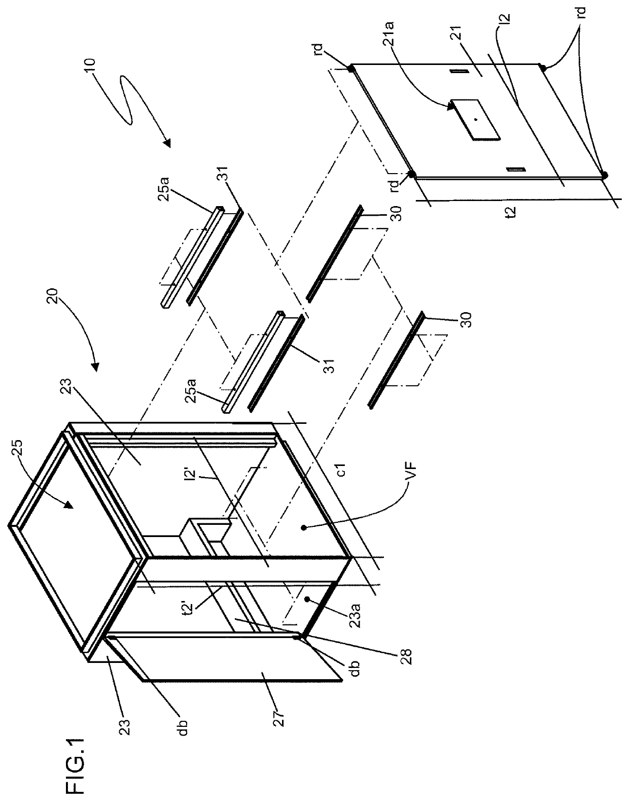
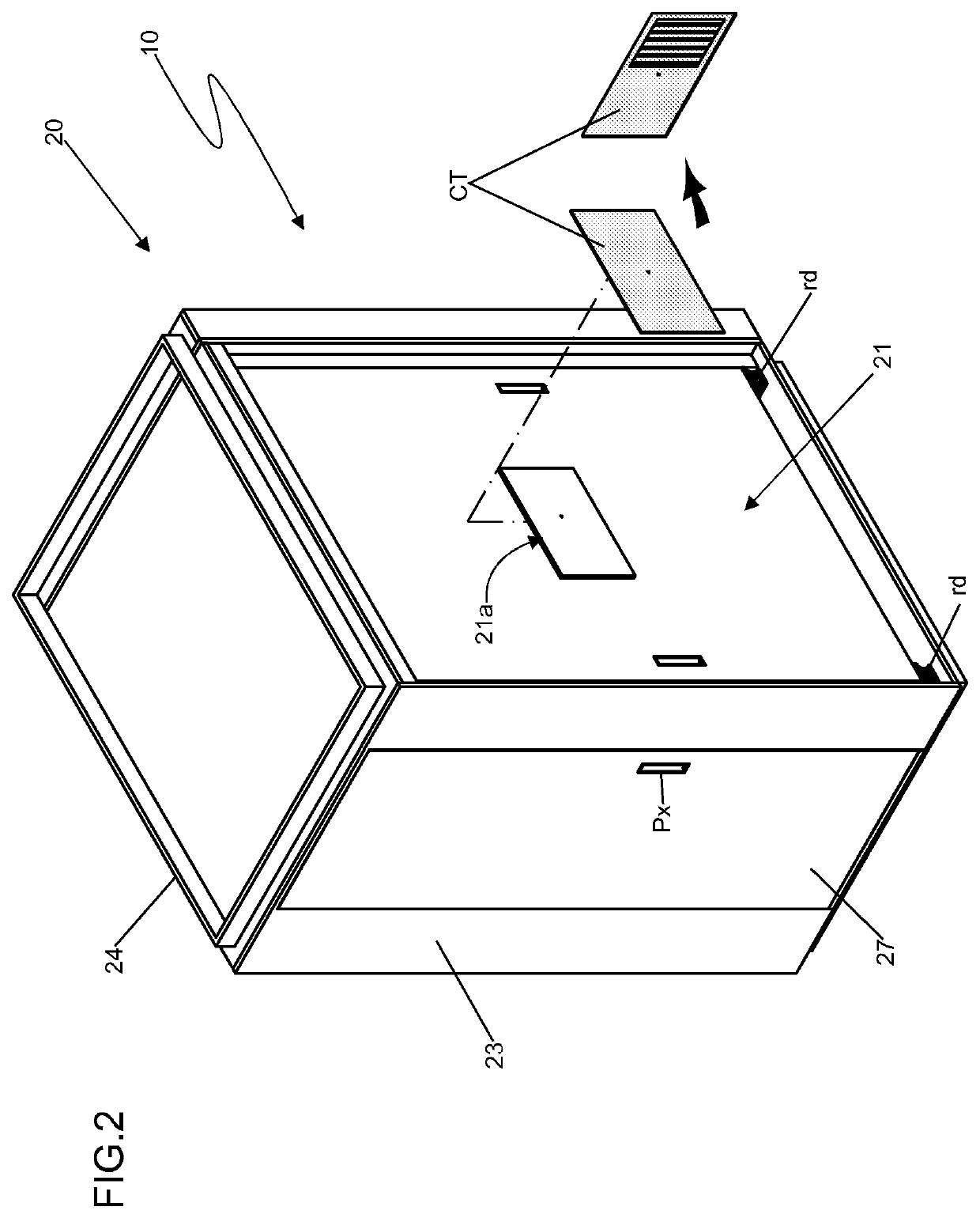
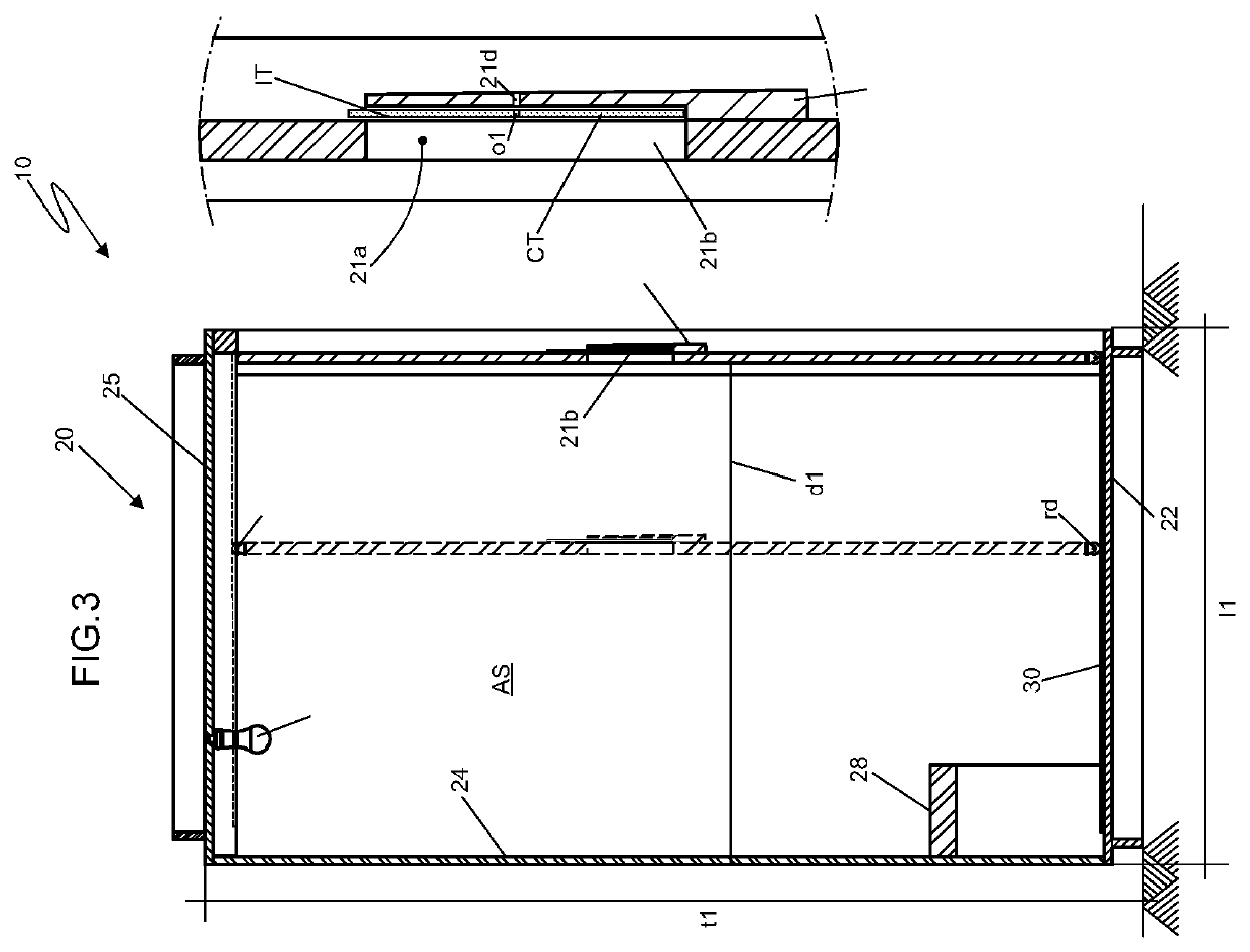
[0021]In respect to the illustrated drawings, this patent of invention refers to “A BOOTH FOR THE PREFERRED VISUAL ACUITY TEST”, more precisely discloses a booth(10) of the type to quantify the visual acuity irrespective of the patient's verbal information (pc) by means of the ‘teller’ technique in such environments as offices and clinics, by a specialized professional.

[0022]According to this invention, said booth(10) comprises a modular structure (20) made in wood, drywall, PVC or another type of material, in a way to make up an isolated environment (AS) for the patient (pc) to perform the preferred acuity test through the reading of ‘Teller’ cards (CT) laid out in the visualization area (21a) foreseen at the central portion of the sliding movable wall (21), through rollers (rd) on rails (30) and (31), installed on the ground (22) and ceiling (25), sustained by profiles (25a). All the modular structure (20) presents a white and opaque tone, as well as a proper lighting (i1), which ...


PUM


Abstract

A booth, for using the Teller technique to quantify visual acuity, irrespective of a patient's verbal ability booth comprises a modular structure, making up an isolated environment for the patient to perform the acuity test through the reading of Teller cards. The patient is accommodated in a visualization area at the central portion of a movable wall sliding via wheels on rails installed on the ground and ceiling by profiles. The modular structure presents a white and opaque tone, as well as its own lighting which is controlled and proper according to the test, in front of a movable wall and coplanar to a rear wall of booth. The movable wall sliding effects the distance adjustment between the patient and the visualization area cards where the minimum distance is equivalent 38 centimeters and the maximum distance is 55 or 84 centimeters as accuracy dictates, according to the patient's features.

Description

TECHNICAL AREA[0001]This patent of invention Discloses a booth for the visual acuity test, preferably in the type performed to quantify the visual acuity, irrespective of the patient's verbal information, more precisely upon the use of the “Teller” technique; the booth for the test of visual acuity was designed for installation in such environments as offices and clinics, and should be used by a specialized professional / specifically, said booth comprises a structure able to provide with a more precise diagnosis, since it features a sliding means of a movable wall, which provides with the spacing adjustment between the ‘Teller’ card in respect to the patient accommodated within the cabin, according to the exam specifications and the features of each patient, in addition to having the booth composing an environment all out of whatever types of visual influences liable to deviate the patient's attention, thus providing a substantial higher accuracy, dependability and reproductivity of...

Claims


Application Information

Patent Timeline
IPC IPC(8): A61B3/032A61B3/00E04H1/12
CPCA61B3/032A61B3/0008A61B3/0083E04H1/12A61B3/185A61B3/028A61B3/06A61B3/0041
Inventor RASSI GABRIEL, LUIS ALEXANDRE
Owner RASSI GABRIEL LUIS ALEXANDRE
Why Eureka
Try Eureka