Method for producing balloon catheter

a technology of balloon catheter and stenosis part, which is applied in the direction of balloon catheter, catheter, etc., can solve the problems of blood vessel injury, difficulty in dilation of stenosis parts,

Pending Publication Date: 2022-10-13
KANEKA CORP
View PDF0 Cites 0 Cited by
  • Summary
  • Abstract
  • Description
  • Claims
  • Application Information

AI Technical Summary

Benefits of technology

[0026]In accordance with the method for producing a balloon catheter according to the present invention, the balloon can be folded with controlling the position of the projecting portion while the projecting portion is hardly crushed by positioning the projecting portion on the inside of a mean circle centered at a gravity center of the tubular object, and having a radius of an average value of a shortest distance from the gravity center of the tubular object to an inside surface of the tubular object and a longest distance from the gravity center of the tubular object to the inside surface of the tubular object on a cross-section perpendicular to the distal-proximal direction of the tubular object in the balloon placement step to placing the balloon in the tubular object and to inflate the balloon by pressurizing the inside of the balloon.

Problems solved by technology

It is difficult to dilate a stenosis part in such a calcified lesion with a general balloon catheter.
Neointima is soft and the surface is slippery at an ISR lesion; as a result, a blood vessel may be hurt by moving the place of a balloon from the lesion in some cases in a case where a general balloon catheter is used and the balloon is inflated.

Method used


Image

  • Method for producing balloon catheter
  • Method for producing balloon catheter
  • Method for producing balloon catheter

Examples


Embodiment Construction

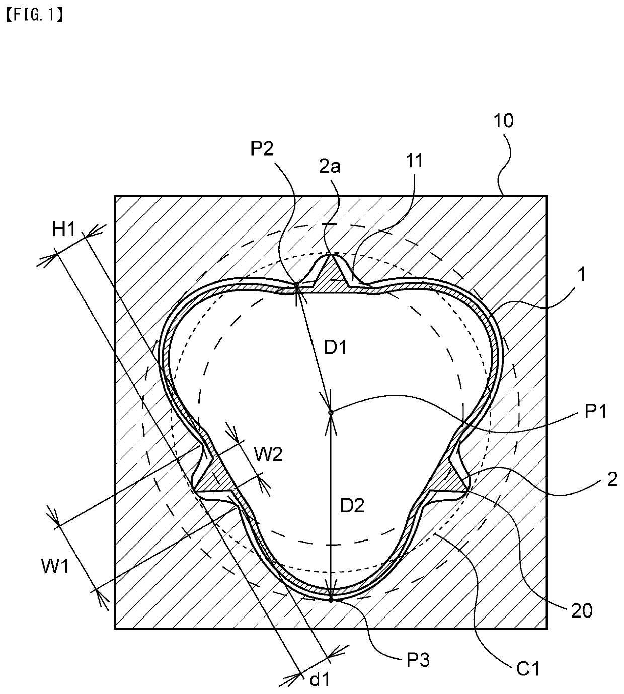
[0034]Hereinafter, the present invention is described in more detail with the following embodiments. The present invention is however not restricted to the following embodiments in any way, and it is possible to work the present invention according to the embodiments with an additional appropriate change within the range of the above descriptions and the following descriptions. Such a changed embodiment is also included in the technical scope of the present invention. Hatching, member symbol or the like may be conveniently abbreviated in each figure in some cases. The specification and the other figure may be referred in such a case. The size of various members in the figures may be different from the actual size in some cases, since priority is given to contributing to the understanding of the feature of the present invention.

[0035]First, the first method for producing a balloon catheter according to the present invention is described.

[0036]FIG. 1 is a cross-sectional view in the b...


PUM

PropertyMeasurementUnit
outer diameteraaaaaaaaaa

Abstract

The method for producing a balloon catheter comprises a tubular object preparing step to prepare a tubular object having a space extending in the distal-proximal direction, a balloon preparing step to prepare a balloon, a balloon placement step to place the balloon in the tubular object and inflate the balloon, and a balloon deflating step to deflate the balloon and form a wing-shaped portion, wherein a projecting portion is placed on within a mean circle C1 centered at a center P1 of the tubular object, and a radius of the mean circle C1 is an average value of a shortest distance D1 from the center P1 of the tubular object to an inside surface P2 of the tubular object and a longest distance D2 from the center P1 of the tubular object to the inside surface P3 of the tubular object on a cross-section in the balloon placement step.

Description

TECHNICAL FIELD[0001]The present invention relates to a method for producing a balloon catheter having a balloon provided with a projecting portion.BACKGROUND ART[0002]It is known that various diseases are caused due to stagnation of blood circulation by stenosis of a blood vessel, which is a flow path for blood circulation in the body. In particular, when the arteria coronaria for supplying blood to the heart becomes stenosed, a severe disease such as angina and myocardial infarction may be produced. Angioplasty such as PTA and PTCA is known as a method for treating a stenosis part of a blood vessel. A balloon catheter is used for expanding a stenosis part in angioplasty. Angioplasty has been widely carried out, since angioplasty is low-invasive therapy without thoracotomy unlike bypass surgery.[0003]A stenosis part hardened by calcification or the like may be formed on the inner wall of the blood vessel in some cases. It is difficult to dilate a stenosis part in such a calcified l...

Claims


Application Information

Patent Timeline
Patent Type & Authority Applications(United States)
IPC IPC(8): A61M25/10
CPCA61M25/1029B29C49/00A61M25/1038
Inventor KOGA, YOJIROKOJIMA, MASAHIRONAKANO, YOSHINORITSUEDA, MASATO
Owner KANEKA CORP
Why Eureka
Try Eureka