
Actuation unit of the articulated lever or cam type provided with a braking unit

a technology of actuation unit and braking unit, which is applied in the direction of brake type, manufacturing tools, clamps, etc., can solve the problems of operator safety, actuation command can occur, and the integrity of the actuation unit itself and of the equipmen

Pending Publication Date: 2022-10-27
PNEUMAX
View PDF0 Cites 0 Cited by
  • Summary
  • Abstract
  • Description
  • Claims
  • Application Information

AI Technical Summary

Benefits of technology

The invention aims to create a linear actuation unit with a braking unit that is reliable and easy to use. The braking seat is designed to prevent the rollers from locking up and causing wear and tear. Additionally, there is a possibility of radial and angular clearance to prevent the head portion from getting locked inside the braking seat.

Problems solved by technology

In these actuation units, anomalous conditions of the actuation command can occur, due for example to the supply of a pressurized fluid in the case of pneumatic command, which can involve risks both for the integrity of the actuation units themselves and of the equipment transported by them, as well as for the safety of the operators who are near the units.
In this second condition, due to the absence of sufficient pressure and under the weight of the equipment constrained to the support arm, the latter can suddenly and violently return to the open position, dragging the equipment therewith.
The Applicant has pointed out that the braking units used in known actuation units have the disadvantage of strong wear due to the friction between the circular or disc surfaces that come into contact with the head of the shaft to stop the rotation thereof.
The Applicant has also pointed out that the known solutions do not generally provide for the possibility of excluding the braking unit—a case that is useful for example during the installation step when the connection to the supply is not yet active—or, if the exclusion is envisaged, an automatic recovery thereof.

Method used


Image

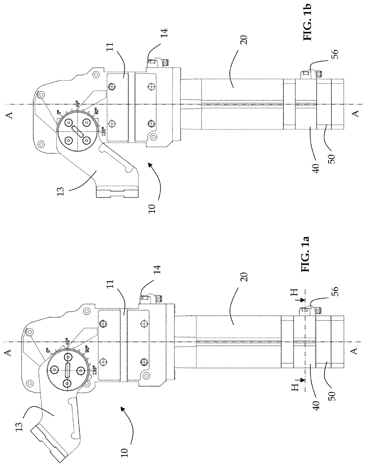
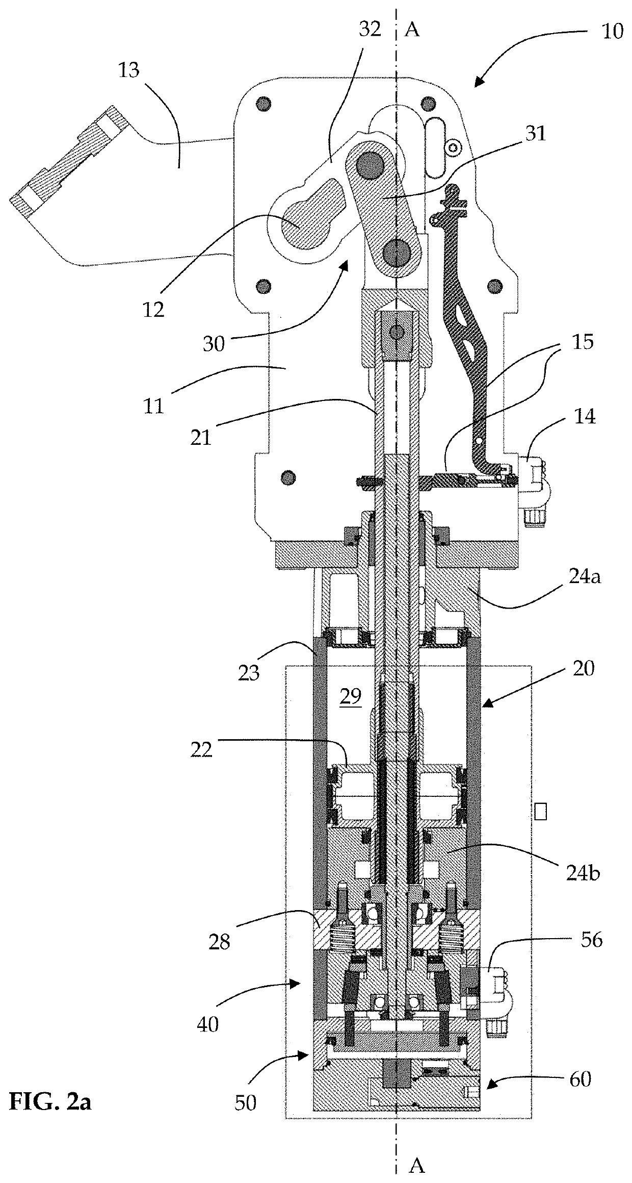
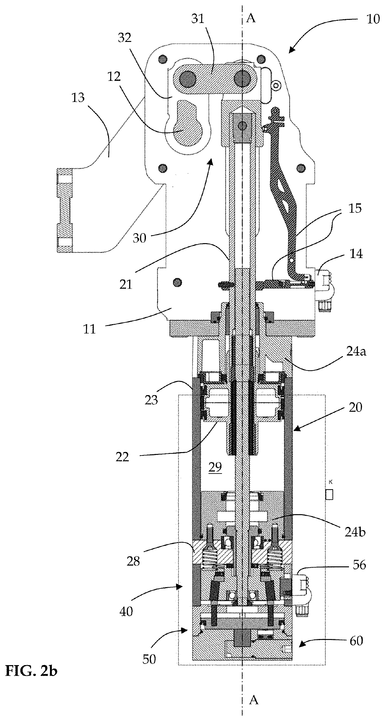
  • Actuation unit of the articulated lever or cam type provided with a braking unit
  • Actuation unit of the articulated lever or cam type provided with a braking unit
  • Actuation unit of the articulated lever or cam type provided with a braking unit

Examples


Embodiment Construction

[0062]In the following description, for the illustration of the figures, identical numbers or reference symbols are used to indicate construction elements with the same function. Further, for illustration clarity, some references may not be repeated in all the figures.

[0063]While the invention is susceptible to various modifications and alternative constructions, certain preferred embodiments are shown in the drawings and are described hereinbelow in detail. However, it is to be understood that there is no intention to limit the invention to the specific embodiment illustrated but, on the contrary, the invention intends to cover all the modifications, alternative and equivalent constructions that fall within the context of the invention as defined in the claims.

[0064]The use of “for example”, “etc.”, “or” indicates non-exclusive alternatives without limitation, unless otherwise indicated. The use of “comprises” and “includes” means “comprises or includes, but not limited to”, unless...


PUM


Abstract

An actuation unit includes an actuating arm pivotable between an open and closed position; a pneumatic cylinder comprising a stem movable linearly along a cylinder axis and configured to control pivoting of the actuating arm; and a closing device that includes a braking unit configured to brake movement of the actuating arm having a surface portion configured to come into contact with at least one braking assembly. The braking assembly is locked against rotation and axially movable between a non-braking and braking configuration. The surface portion is in a non-orthogonal arrangement with respect to the cylinder axis and the braking assembly includes a plurality of rollers retained in the braking assembly with clearance at least with respect to a radial movement thereof, the rollers being able to assume a first radial configuration not in contact with the surface portion and a second radial configuration in contact with the surface portion.

Description

TECHNICAL FIELD[0001]The present invention generally relates to an actuation unit of the articulated lever or cam type provided with a braking unit configured to ensure the parking of an actuator of the actuation unit in a predetermined position. In particular, the present invention relates to rotating or oscillating units typically used in the field of sheet metal working, for example for the construction of motor vehicle bodies.BACKGROUND[0002]In the field of the construction of motor vehicle bodies, it is known to use actuation units of the rotating or oscillating type for the movement of a support arm to which the grippers for locking the sheets to be welded are constrained, maintaining the support arm firmly locked in a certain position.[0003]For this purpose, the known actuation units comprise a closing device capable of bringing a support arm connected to this device into an exact closed operative position and, once reached, keeping it in this position, triggering a mechanism...

Claims


Application Information

Patent Timeline
IPC IPC(8): F15B15/26F16D63/00F16D66/00
CPCF15B15/262F16D63/008F16D66/00F16D2066/003B25B5/122F15B15/264
Inventor BOTTACINI, ROSSELLA
Owner PNEUMAX
Learn More