Visibility of Mechanical Thrombectomy Device During Diagnostic Imaging

a technology of mechanical thrombus and diagnostic imaging, which is applied in the field of endovascular medical system, can solve the problems of relatively poor visibility and relatively low radiopacity of mechanical thrombus under fluoroscopic imaging, and achieve the effect of improving visibility

Pending Publication Date: 2022-11-10
NEURAVI
View PDF0 Cites 1 Cited by
  • Summary
  • Abstract
  • Description
  • Claims
  • Application Information

AI Technical Summary

Benefits of technology

The present invention relates to a device that can be used to remove blood clots from the body. The invention improves visibility during diagnostic imaging.

Problems solved by technology

Despite these beneficial characteristics, one significant drawback associated with using a shape memory alloy for manufacture of the mechanical thrombectomy device is its relatively poor visibility under fluoroscopic imaging, that is, its relatively low radiopacity.

Method used


Image

  • Visibility of Mechanical Thrombectomy Device During Diagnostic Imaging
  • Visibility of Mechanical Thrombectomy Device During Diagnostic Imaging
  • Visibility of Mechanical Thrombectomy Device During Diagnostic Imaging

Examples


Embodiment Construction

[0055]The terms “distal” or “proximal” are used in the following description with respect to a position or direction relative to the treating physician or medical interventionalist. “Distal” or “distally” are a position distant from or in a direction away from the physician or interventionalist. “Proximal” or “proximally” or “proximate” are a position near or in a direction toward the physician or medical interventionalist. The terms “occlusion”, “clot” or “blockage” are used interchangeably.

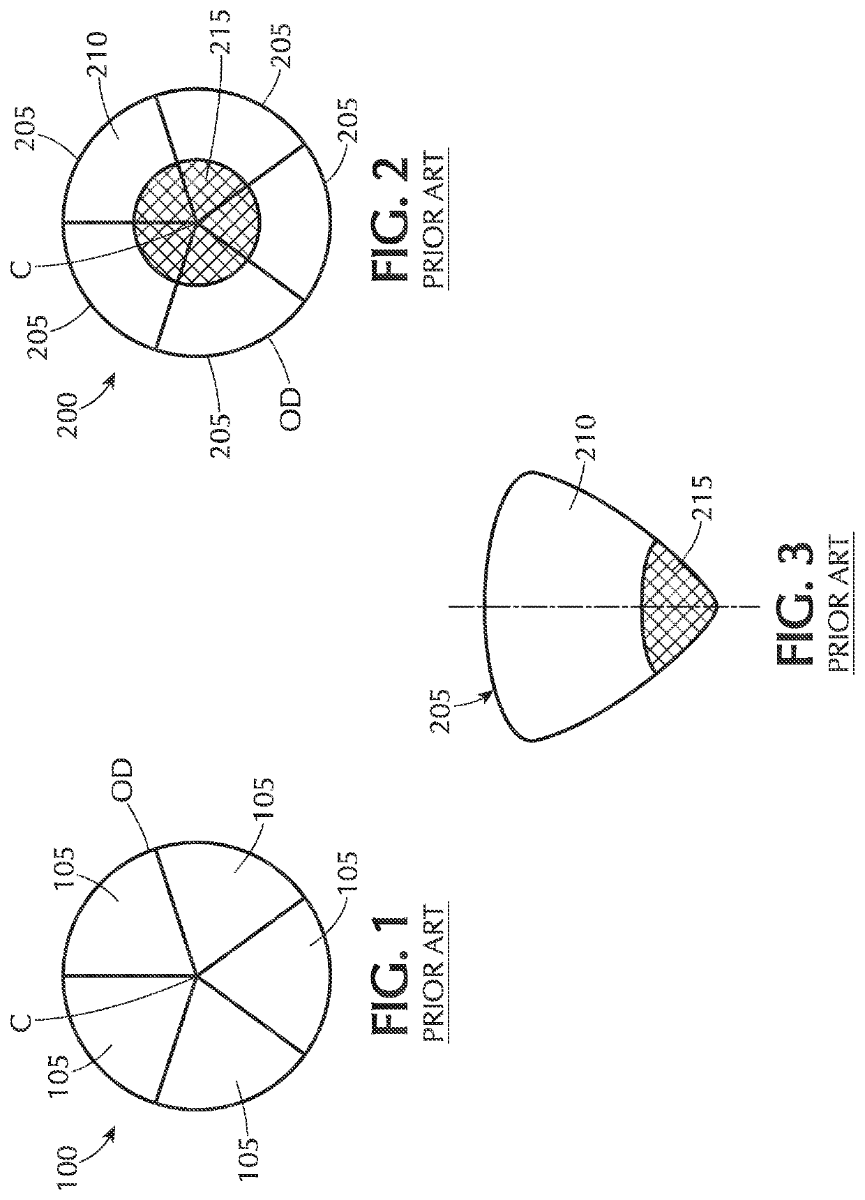
[0056]Referring to FIG. 2, a radial cross-sectional view of an exemplary Prior Art drawn filled tube (DFT) composite wire 200 to produce a mechanical thrombectomy device is illustrated. The wire in FIG. 2 has an inner core 215 made of a first biocompatible material surrounded by an outer layer 210 of a second biocompatible material that differs from the first material. The first material forming the inner core 215 is made of a radiopaque material, that is, a material that is opaque to one or ano...


PUM


Abstract

An expandable mechanical device for use during a thrombectomy medical procedure having enhanced visibility during imaging. Furthermore, the configuration of the eyelet and / or strut optimizes retention of the marker in the eyelet during the medical procedure without increasing overall profile of strut.

Description

CROSS-REFERENCE TO RELATED APPLICATIONS[0001]This application is a divisional application of U.S. patent application Ser. No. 16 / 441,537, filed Jun. 14, 2019, which is herein incorporated by reference in its entirety.BACKGROUND OF THE INVENTIONField of the Invention[0002]The present invention relates to an endovascular medical system. In particular, the present invention is directed to an improved mechanical thrombectomy device with enhanced visibility during diagnostic imaging.Description of Related Art[0003]Acute ischemic stroke is caused by a thrombotic or embolic occlusion (e.g., blockage) in a cerebral artery of the brain. The occlusion is typically caused by a blood clot liberated from another part of the body which travels in an anterograde direction (in the direction of normal blood flow) through the vessel and eventually become lodged in the cerebral artery of the brain. Clots are subject to a pulsatile pressure gradient (i.e., systemic blood pressure acting on the proximal...

Claims


Application Information

Patent Timeline
Patent Type & Authority Applications(United States)
IPC IPC(8): A61B17/221
CPCA61B17/221A61B2090/3966A61F2/82A61F2/915A61F2002/91575A61F2250/0098A61B2017/2215A61B2017/00867A61B2017/00831A61B2017/2212A61B90/39A61B17/3207A61B2017/22094A61B2017/00915A61B2017/22001A61B2017/320716
Inventor VALE, DAVIDDUFFY, AIDANKELLY, RONALDCONWAY, SHANECASEY, BRENDANO'MALLEY, THOMAS
Owner NEURAVI
Why Eureka
Try Eureka