Optical film, polarizing plate, image display device, and optical film selection method

a technology of optical film and polarizing plate, which is applied in the direction of optical elements, polarising elements, instruments, etc., can solve the problems of easy stretching direction tearing and observed rainbow pattern unevenness, and achieve the effect of efficiently selecting, and suppressing rainbow pattern unevenness

Pending Publication Date: 2022-11-17
DAI NIPPON PRINTING CO LTD
View PDF0 Cites 0 Cited by
  • Summary
  • Abstract
  • Description
  • Claims
  • Application Information

AI Technical Summary

Benefits of technology

The present disclosure is related to an optical film that can prevent rainbow unevenness when viewed with the naked eyes. The patent aims to provide a method for efficiently selecting an optical film that can effectively prevent rainbow unevenness without increasing the in-plane phase difference. The technical effect of this patent is to improve the image quality of image display devices and to enhance the overall viewing experience for users.

Problems solved by technology

In the case of disposing a stretched plastic film on a polarizer, a problem is that rainbow pattern unevenness is observed due to the stretched plastic film disturbing the polarization state of the linearly polarized light that has passed through the polarizer.
Further, a stretched plastic film having large in-plane phase difference is generally uniaxially stretched and therefore has problems such as easy tearing in the stretching direction.

Method used


Image

  • Optical film, polarizing plate, image display device, and optical film selection method
  • Optical film, polarizing plate, image display device, and optical film selection method
  • Optical film, polarizing plate, image display device, and optical film selection method

Examples


example 1

[0417]Onto the biaxially stretched polyester film 1 produced in section 2 above, a coating solution for forming hard coating layer prescribed as follows was applied, followed by drying at 70° C. for 1 minute, to evaporate the solvent. Subsequently, a hard coating layer (dry thickness: 10 μm) was formed by UV irradiation (100 mJ / cm2).

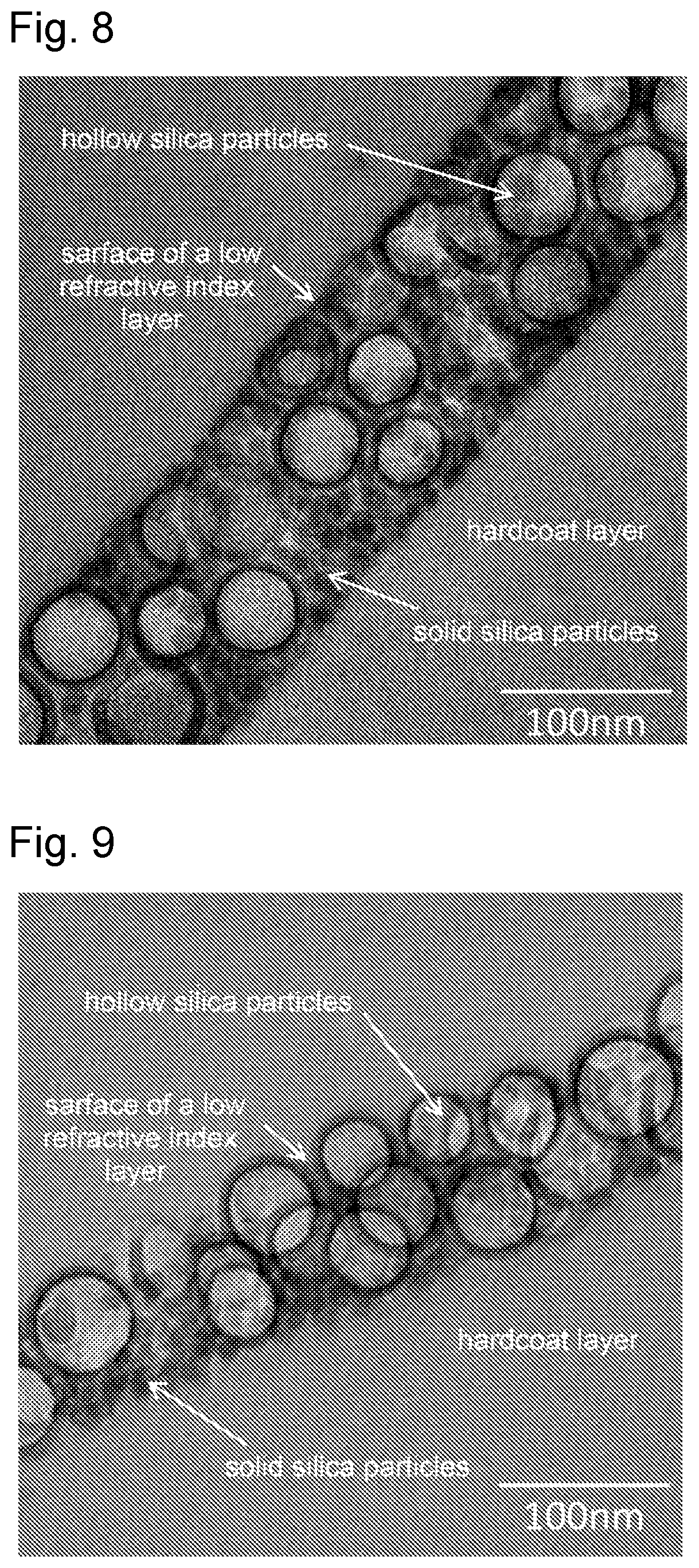
[0418]A coating solution 1 for forming low-refractive index layer prescribed as follows was applied onto the hard coating layer, followed by drying at 60° C. for 1 minute, to evaporate the solvent. Subsequently, a low-refractive index layer (dry the thickness of 100 nm) was formed by UV irradiation (200 mJ / cm2), to obtain an optical film of Example 1.

[0419]Ultraviolet curable acrylate-containing composition: 22 parts by mass (Nippon Kayaku Co., Ltd., product name “KAYARAD PET-30”, solid content: 100%)

[0420]Ultraviolet curable acrylate-containing composition: 17 parts by mass (DKS Co. Ltd., product name “NewFrontier R-1403M”, solid content: 80%)

[0421]Fluo...

examples 2 and 3

[0431]The optical films of Examples 2 and 3 were obtained in the same manner as in Example 1, except that the biaxially stretched polyester film 1 was changed to the biaxially stretched polyester films 3 and 4 prepared in section “2” above.

reference example 1

[0434]A simple substance of the biaxially stretched polyester film 3 (film with no hard coating layer and no low-refractive index layer formed on the biaxially stretched polyester film 3) was used as the optical film of Reference Example 1.


PUM

PropertyMeasurementUnit
refractive indexaaaaaaaaaa
areaaaaaaaaaaa
areaaaaaaaaaaa

Abstract

Provided is an optical film that can suppress rainbow unevenness when viewed with the naked eyes without increasing the in-plane phase difference. The optical film has a low-refractive index layer on a plastic film, the plastic film is a biaxially stretched plastic film with an in-plane phase difference of 2500 nm or less, the low-refractive index layer is located on the outermost surface, and the optical film has a region in which ΔEab satisfies specific conditions, wherein the ΔEab is calculated from the differences between the L* value, the a* value, and the b* value obtained by measuring a laminate 1 including the optical film, the polarizer, and the surface light source under specific conditions and the L* value, the a* value, and the b* value obtained by measuring a laminate 2 including the polarizer and the surface light source under specific conditions, respectively.

Description

TECHNICAL FIELD[0001]The present disclosure relates to an optical film, a polarizing plate, an image display device, and a method for selecting an optical film.BACKGROUND ART[0002]For optical members such as image display devices, various optical plastic films are often used. For example, a plastic film is used for protecting a polarizer constituting the polarizing plate in an image display device having a polarizing plate on a display element.[0003]Plastic films for image display devices used as such polarizer protective films preferably have excellent mechanical strength. Therefore, stretched plastic films are preferably used as plastic films for image display devices.[0004]In the case of disposing a stretched plastic film on a polarizer, a problem is that rainbow pattern unevenness is observed due to the stretched plastic film disturbing the polarization state of the linearly polarized light that has passed through the polarizer. In order to solve such a problem, techniques such ...

Claims


Application Information

Patent Timeline
Patent Type & Authority Applications(United States)
IPC IPC(8): G02B5/30
CPCG02B5/3083G02B5/3025G02F1/133528G02B5/3033G02F1/133531G02F1/133634G02B1/111G02B1/14G02B5/3041B29C55/023B32B7/023H05B33/02B32B2307/42H10K59/00H10K50/868G02F1/13363
Inventor KUBOTA, SHOSEITANAKA, YOSHIKOISHII, NORIOKURODA, TAKASHISEGAWA, HIROAKIUSHIYAMA, AKINOBU
Owner DAI NIPPON PRINTING CO LTD
Why Eureka
Try Eureka