Polarizing plate and image display device

A polarizing plate and polarizing element technology, applied in optics, optical elements, polarizing elements, etc., can solve the problems of uneven display, poor moisture and heat resistance of cellulose ester film, reduced polarization function or color and luster, etc. Shows the effect of suppressing unevenness and excellent adhesion

Inactive Publication Date: 2015-11-25
FUJIFILM CORP
View PDF13 Cites 2 Cited by
  • Summary
  • Abstract
  • Description
  • Claims
  • Application Information

AI Technical Summary

Problems solved by technology

However, the cellulose ester film has poor heat and humidity resistance, and if the hard coat film is used as a polarizer protective film in a high-temperature and high-humidity environment, there is a disadvantage that polarizer functions such as polarizing function and color will be reduced.
Therefore, when such a polarizer using a hard coat film as a polarizer protective film is incorporated into an image display device, there is a problem of display unevenness after heat treatment over time.

Method used


Image

  • Polarizing plate and image display device
  • Polarizing plate and image display device
  • Polarizing plate and image display device

Examples


Embodiment 1

[0244]

[0245] (raw material polyester 1)

[0246]As shown below, the raw material polyester 1 ( Sb catalyst system PET).

[0247] (1) Esterification reaction

[0248] In the first esterification reaction tank, 4.7 tons of high-purity terephthalic acid and 1.8 tons of ethylene glycol were mixed for 90 minutes to form a slurry, which was continuously supplied to the first esterification reaction tank at a flow rate of 3800 kg / h. Furthermore, an ethylene glycol solution of antimony trioxide was continuously supplied, and the reaction was carried out at an average residence time of about 4.3 hours under stirring at a temperature of 250° C. in the reaction tank. At this time, antimony trioxide was added continuously so that the addition amount of antimony (Sb) might become 150 ppm in element conversion value.

[0249] The reactant was transferred to the second esterification reaction tank, and the reaction was carried out at a temperature of 250° C. in the reaction tank and ...

Embodiment 2~ Embodiment 9

[0338] The polarizing plates of Examples 2 to 9 were produced in the same manner as in Example 1 except that the production conditions were changed as shown in Table 1 below when the polarizing plate of Example 1 was produced. In addition, Re and Rth of the polyester film were controlled to the values ​​in Table 1 below by setting the stretching conditions in the width direction as polarized light.

Embodiment 10

[0340] (easy-adhesive layer including emulsion)

[0341] 35% of UV absorbing emulsion (Nu-Kote UVA-204W: manufactured by Shin-Nakamura Chemical Industry Co., Ltd.) was mixed with the easy-adhesive coating liquid H1 for the easy-adhesive layer on the hard coat side, except Other than that, it carried out similarly to Example 1, and produced the polarizing plate of Example 10.


PUM

PropertyMeasurementUnit
widthaaaaaaaaaa
particle sizeaaaaaaaaaa
thicknessaaaaaaaaaa

Abstract

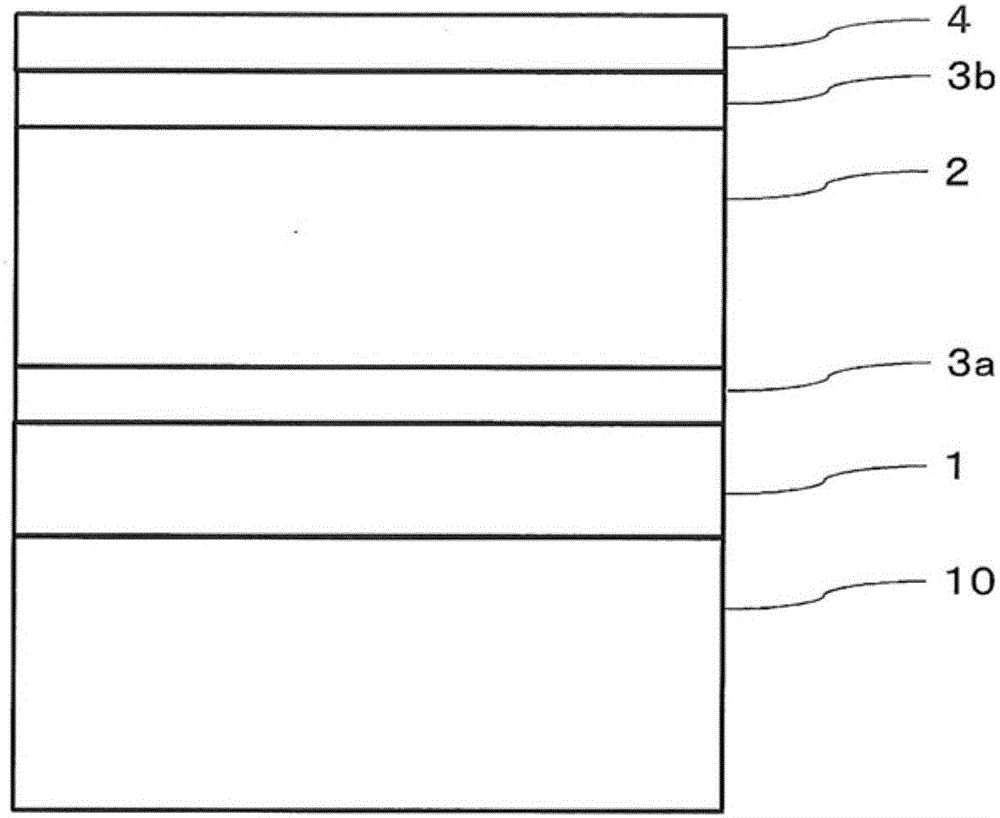
The present invention has in this order: a protective film; a polarizer that contains polyvinyl alcohol; a polyester film; a hard coat layer side highly adhesive layer; and a hard coat layer. The polyester film extends in the direction of width, and the polyester film width is 1.4 m or greater. The retention (Re) in a direction within the surface of the polyester film is 4000 - 20,000 nm, and an angle formed between the direction of maximum modulus of elasticity within the surface of the polyester film and the direction of the axis of absorption of the polarizer is 90 ± 25° for both an end part and center in the direction of width of the polyester film. The melting sub-peak temperature (Tsm) for the polyester film is 140 - 220°C. A band shaped polarizing plate has superior adherence after the passage of time with heat and humidity and after exposure to light of the polyester film and the hard coat layer which is laminated on the polyester film, which serve as protective films for the polarizer. Display variations can be suppressed during integration into an image display device after the passage of time with heat in humidity, and iridescent irregularities are suppressed during integration into the image display device.

Description

technical field [0001] The present invention relates to a polarizing plate and an image display device having a protective film in which a hard coat layer is formed on the surface of a polyester film. Background technique [0002] Liquid crystal display (LiquidCrystalDisplay, LCD), plasma display (PlasmaDisplayPanel, PDP), electroluminescence display (organic electroluminescence display (OrganicElectroluminescenceDisplay, OELD) or inorganic electroluminescence display (InorganicElectroluminescenceDisplay, IELD)), field emission display (FieldEmissionDisplay , FED), touch screen, electronic paper and other image display devices are equipped with polarizing elements on the display screen side of the image display panel, and then an optical laminate with functions such as antireflection and hard coating is provided on the outermost surface. [0003] Conventionally, a film containing a cellulose ester typified by triacetyl cellulose has been used as a light-transmitting base mat...

Claims


Application Information

Patent Timeline
Patent Type & Authority Applications(China)
IPC IPC(8): G02B5/30B32B7/02B32B27/30B32B27/36C08K5/00G02B1/14G02F1/1335
CPCB32B7/02B32B7/12B32B27/30B32B27/36B32B2307/42B32B2457/20C08K5/005G02B1/105G02B5/305G02F1/133502G02F1/133528G02F2202/28G02B1/14
Inventor 二村恵朗野村达也小林孝史中居真一
Owner FUJIFILM CORP
Why Eureka
Try Eureka