

Hall-effect sensor having integrally molded frame with printed conductor thereon
a technology of printed conductors and sensors, applied in the field of hall-effect sensors, can solve the problems of inferior sensor sensitivity and sensor not being suitable for mass production
- Summary
- Abstract
- Description
- Claims
- Application Information
AI Technical Summary
Problems solved by technology
Method used
Image

Examples
first embodiment
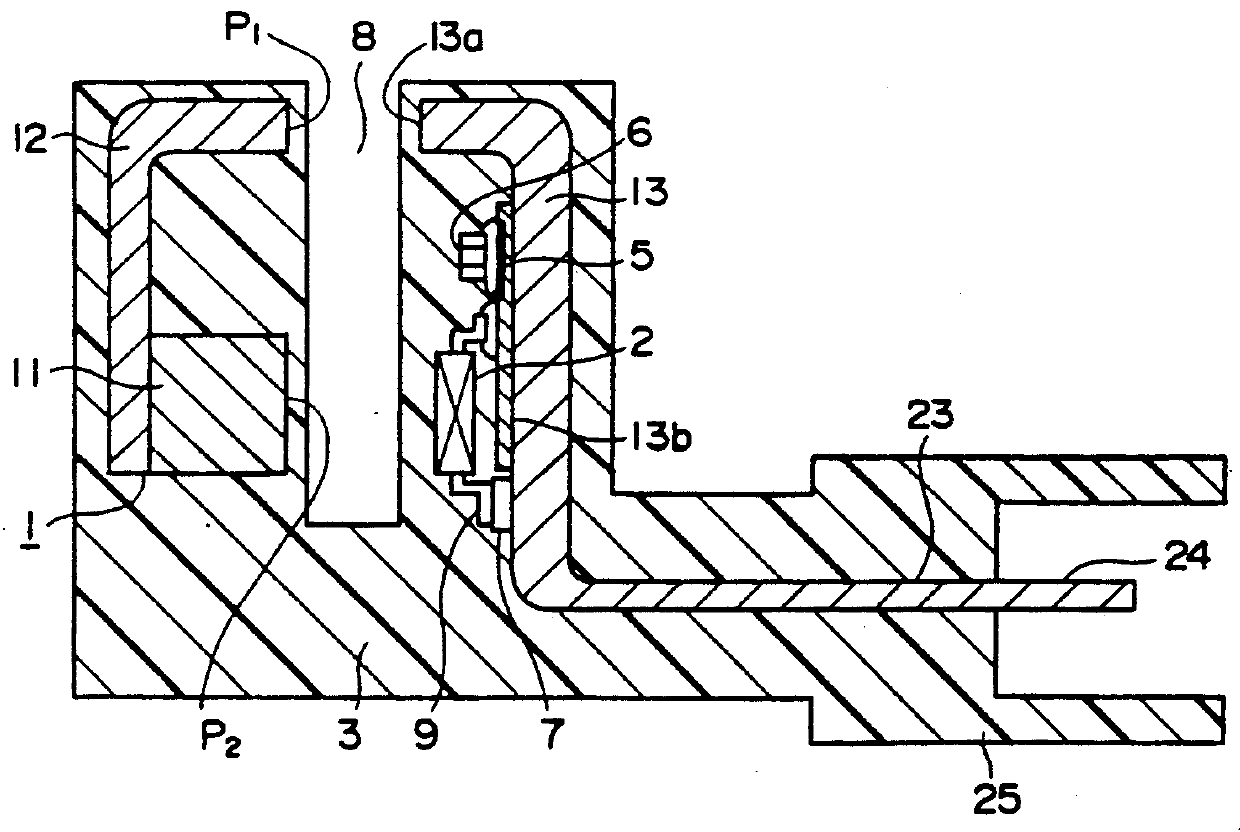
FIG. 4 shows another example of the In the figure, reference numeral 1 designates a flux generating member, which is comprised of a magnet 11, a flux guide 12 kept in contact with the magnet 11, and a flux guide 13 which is positioned to face in opposite directions of the magnet 11 and the flux guide 12 with a gap 8 between. A pole P.sub.1 of the flux guide 12 and a pole P.sub.2 of the magnet 11 which has a function opposite to the pole P.sub.1 are arranged in the same direction. Portions of the flux guide 13 shown by 13a and 13b are positioned to face in opposite directions of the poles P.sub.1 of the flux guide 12 and the P.sub.2 of the magnet 11, respectively. This facing portion 13a is formed as one bent-end portion of the flux guide 13, and so is the facing portion 13b as a plane portion of the flux guide 13. There is applied the insulative film 5 onto the facing portion 13b. The flux guide 13 is provided with an insert conductor 23 for fetching an electric signal converted by...
second embodiment
FIG. 5 shows a sensor of the second embodiment. Reference numeral 1 in the figure shows a flux generating member which is comprised of a magnet 11 and a flux guide 12 which is kept in contact with the magnet 11. The flux generating member 1 is integrally locked to a molded frame 3 made of a mold resin. The molded frame 3 has a fixing portion 34 for fixing the Hall element 2. In the molded frame 3, there is fitted an insert conductor 23, which is connected to a printed conductor 7 being formed on the fixing portion 34 in the molded frame 3. At one end of the molded frame 3, there is formed a connector 25. The Hall element 2 is disposed in a position below the magnet 11 with a gap 8 between. A lead wire 9 of the Hall element 2 is electrically connected to the printed conductor 7 and to the insert conductor 23 by a soldering paste 4. An electronic part 6 such as a surge protection element is provided in the fixing portion 34 of the molded frame 3 with the soldering paste 4 between. An ...
third embodiment
FIGS. 10 and 11 show the third embodiment. In those figures, reference numeral 1 designates a flux generating member which is comprised of a magnet 11, a flux guide 12, a a flux guide 13. This flux generating member 1 is integrally positioned and locked in a molded frame 3. The molded frame 3 has a locking portion 3a for a plate 31, a locking portion 3b for the flux generating member 1 (flux guide 12), and a housing portion 3c for a Hall element 2 and the like. An insert conductor 23 is fitted in the molded frame 3, and at one end of the molded frame 3, there is formed a connector 25. The plate 31 made of metal, plastic or the like is arranged in a position to face the magnet 11 with a gap 8 between and is locked to the locking portion 3a. On the other surface of the plate 31 which is not facing the magnet 11, there is applied an insulative film 5, onto which is formed a printed conductor 7. The Hall element 2 and such an electronic part 6 as a surge protection element are connected...
PUM
| Property | Measurement | Unit |
|---|---|---|
| magnetic flux | aaaaa | aaaaa |
| electrically | aaaaa | aaaaa |
| Hall effect | aaaaa | aaaaa |
Abstract
Description
Claims
Application Information