Single-use, bullet-proof shield

a shield and single-use technology, applied in the field of single-use, bullet-proof shields, can solve the problems of injuring individuals located in adjoining rooms, damage to physical property, injuries,

Inactive Publication Date: 2000-01-04
TEKORIUS PAUL
View PDF15 Cites 30 Cited by
  • Summary
  • Abstract
  • Description
  • Claims
  • Application Information

AI Technical Summary

Benefits of technology

It is another object of the invention to provide a shield that is attractive, inexpensive to manufacture and appears as a standard wall hanging.
It is a further object of the invention to provide such a shield that is easy and convenient to use.
These and other objects are met by providing a bullet-proof shield, designed to stop the penetration of a bullet when accidently discharged from a firearm. The bullet-proof shield comprises at least one back, non-penetrable layer, a middle energy-absorbing layer and a front anti-shattering layer all housed within an attractive outer frame. The shield has an attractive appearance which enables it to appear as a typical wall hanging in a building. The back, non-penetrable layer is made of metal sufficiently durable to undergo plastic deformation and to stop the penetration of a high velocity bullet. The middle energy-absorbing layer is made of wood with randomly aligned grain. The front layer is made of anti-shattering, energy-absorbing material designed to prevent the wood and metallic particles from rebounding outward toward the user when an accidental discharge occurs. In one embodiment, the front layer is made of transparent material and has an optional aiming sheet disposed between the outer surface of the wood layer and the inner surface of the front layer. The aiming sheet has targeting indicia printed thereon which directs the user to aim the gun towards the center of the shield when cleaning the firearm or loading or unloading bullets.

Problems solved by technology

Accidental firearm discharges are a common cause of damage to physical property and injuries.
When discharges do occur, they often injure individuals located in adjoining rooms when the ammunition travels through walls, floors and ceilings.

Method used


Image

  • Single-use, bullet-proof shield
  • Single-use, bullet-proof shield
  • Single-use, bullet-proof shield

Examples


Embodiment Construction

)

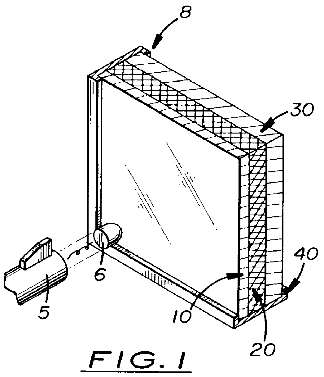
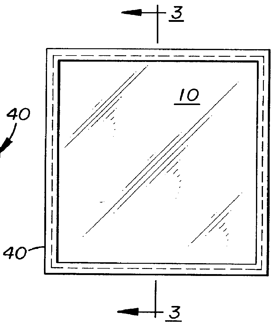
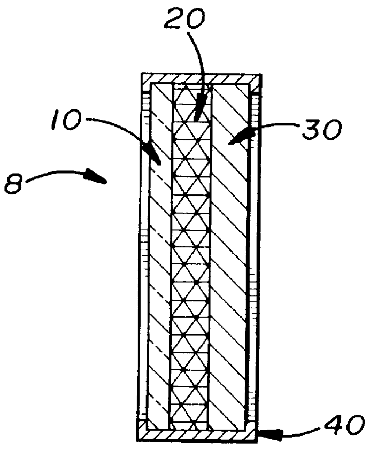
Shown in the accompanying FIGS. 1-4, there is shown a shield, generally referred to as 8, designed to stop the penetration of a bullet 6 when accidently discharged from a firearm 5. The bullet-proof shield 8 comprises a front layer 10, a middle layer 20, and a back layer 30 all housed within an attractive outer frame 40. The shield 8 has an attractive appearance which enables it to be used as a wall hanging or as a piece of furniture. The middle layer 20 is designed to partially absorb the energy of a high velocity bullet 6 while the back metallic layer 30 is designed to stop the penetration.

The front layer 10 is made of an energy-absorbing material designed to prevent wood and metallic particles from rebounding outward toward the user when an accidental discharge occurs. In one embodiment, the layer 10 is a sheet of transparent, polycarbonate material approximately one-sixteenth inch thick. As shown in FIG. 4, an optional aiming sheet 50 may be disposed between the outer surface o...


PUM


Abstract

An attractive, wall-mounted bullet-proof shield, designed to stop the penetration of a bullet when accidently discharged from a firearm. The bullet-proof shield comprises a back layer made of metallic material, a middle layer made of wood, and a front layer made of plastic, all housed within an outer frame. The shield has an attractive appearance which enables it to be used as a wall hanging or as a piece of furniture. The middle layer is designed to partially absorb the energy of a discharged bullet while the back layer is metallic and designed to stop the penetration of a bullet. The front layer is made of an anti-shattering material designed not to shatter and to prevent wood and metallic particles from rebounding outward toward the user. In one embodiment, the front layer is transparent and an optional aiming sheet is disposed between the outside surface of the wood layer and the inside surface if the front layer. The aiming sheet has targeting indicia printed thereon which reminds the user where to aim the gun towards the center of the shield when cleaning the firearm or loading or unloading bullets.

Description

1. Field of the InventionThis invention relates to firearm shields and, more particularly, to shield designs that protect against injury or damage caused by accidental discharge of a firearm.2. Description of the Related ArtAccidental firearm discharges are a common cause of damage to physical property and injuries. Typically, such discharges occur when ammunition is loaded or unloaded from the firearm or when the firearm is being cleaned. When discharges do occur, they often injure individuals located in adjoining rooms when the ammunition travels through walls, floors and ceilings.What is needed is an attractive, inexpensive bullet-proof shield designed to be used in a building to which the muzzle of the firearm may be pointed when the firearm is being loaded, unloaded or cleaned. Ideally, the shield should be light, capable of being wall-mounted or placed on a dresser or night stand so that it appears as a standard wall hanging or furniture yet sufficiently durable to stop the pe...

Claims


Application Information

Patent Timeline
Patent Type & Authority Patents(United States)
IPC IPC(8): F41H5/00F41J1/00F41J1/14F41H5/04F41J13/02
CPCF41H5/0442F41J13/02
Inventor TEKORIUS, PAUL
Owner TEKORIUS PAUL
Why Eureka
Try Eureka