Electronic control for a hydraulically activated, electronically controlled injector fuel system and method for operating same

a technology of electronic control and fuel injection, which is applied in the direction of electric control, fuel injecting pumps, machines/engines, etc., can solve the problems of reducing affecting the repeatability of the fuel injection system, and creating undue stress on the mechanical components of the injector

Inactive Publication Date: 2000-01-18
CATERPILLAR INC
View PDF26 Cites 31 Cited by
  • Summary
  • Abstract
  • Description
  • Claims
  • Application Information

AI Technical Summary

Problems solved by technology

However, current levels that are too high for too long will result in undesirable consequences.
As is described in more detail below, higher current levels for too long of a duration can also create undue stress on mechanical components of the injector and also degrade its repeatability.
Higher power components and / or more robust mechanical components will increase the cost of the injector driver design.
The degradation of the injector repeatability will adversely affect injector performance.
If the ball is not held to the high pressure seat, then the injection event will not be consistent and could inconsistently fuel the engine.
However, that pre-selected pull-in current duration time may be longer than is required to provide the desired response in other, less severe, operating conditions.

Method used


Image

  • Electronic control for a hydraulically activated, electronically controlled injector fuel system and method for operating same
  • Electronic control for a hydraulically activated, electronically controlled injector fuel system and method for operating same
  • Electronic control for a hydraulically activated, electronically controlled injector fuel system and method for operating same

Examples


Embodiment Construction

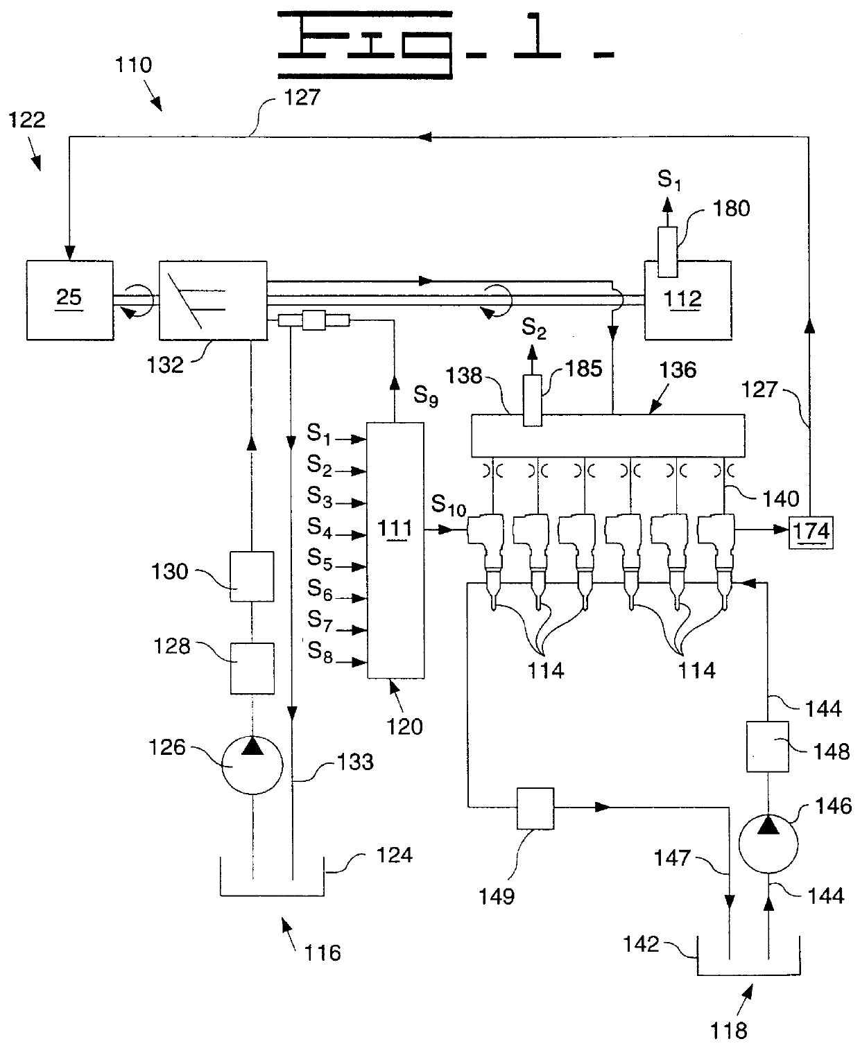
Referring now to FIG. 1, there is shown an embodiment of a hydraulically-actuated electronically-controlled fuel injection system 110 in an example configuration as adapted for a direct-injection diesel-cycle internal combustion engine 112. Fuel system 110 includes one or more hydraulically-actuated electronically-controlled fuel injectors 114, which are adapted to be positioned in a respective cylinder head bore of engine 112. Fuel system 110 includes an apparatus or means 116 for supplying actuation fluid to each injector 114, an apparatus or means 118 for supplying fuel to each injector, a computer 120 for electronically controlling the fuel injection system and an apparatus or means 122 for re-circulating actuation fluid and for recovering hydraulic energy from the actuation fluid leaving each of the injectors.

The actuating fluid supply means 116 preferably includes an actuating fluid sump 124, a relatively low pressure actuating fluid transfer pump 126, an actuating fluid coole...


PUM


Abstract

An apparatus and method for varying the duration of current levels of a fuel injection signal used in connection with an electronically controlled hydraulic actuator unit injector fuel system is disclosed. The apparatus and method varies the duration of the pull-in current of the fuel injection signal delivered to the unit injector based on sensed engine parameters, which preferably include a sensed temperature of the engine and engine speed.

Description

DESCRIPTION1. Technical FieldThe present invention relates generally to hydraulically actuated electronically controlled fuel injection, and more particularly, to an electronic control for varying the duration time of current levels of a fuel injection signal based on sensed engine parameters.2. Background ArtElectronically controlled fuel injectors are well known in the art. An example of a hydraulically actuated electronically controlled unit injector fuel system is shown in U.S. Pat. No. 5,191,867 issued to Glassey on Mar. 9, 1993.As is known in the art, to control the power and emissions output of an internal combustion engine precisely, it is necessary to control the timing and quantity of fuel injected into the engine cylinders. Electronically controlled fuel injectors typically inject fuel into a specific engine cylinder as a function of an injection signal received from an electronic controller. When using hydraulically actuated electronically controlled unit injectors (here...

Claims


Application Information

Patent Timeline
Patent Type & Authority Patents(United States)
IPC IPC(8): F02D41/20F02M57/02F02M57/00F02D41/38F02M47/00F02M47/02
CPCF02D41/20F02M57/025F02D41/3809F02D2041/2003F02D2041/2031
Inventor COWDEN, GARY L.MCGEE, BRIAN G.PUCKETT, DANIEL R.TIMMONS, JOHN P.
Owner CATERPILLAR INC
Why Eureka
Try Eureka