Microwave distillation apparatus, and vessel-biasing assembly

a technology of distillation apparatus and vessel, which is applied in the direction of electric/magnetic/electromagnetic heating, separation processes, evaporation, etc., can solve the problems of inconvenient and time-consuming distillation process, inability to heat a liquid sample in time, and inability to achieve the effect of quick and efficient heat a liquid sampl

Inactive Publication Date: 2000-01-18
ARMSTRONG BERNARD
View PDF11 Cites 9 Cited by
  • Summary
  • Abstract
  • Description
  • Claims
  • Application Information

AI Technical Summary

Benefits of technology

to provide a distillation apparatus which utilizes microwave energy to quickly and efficiently heat a liquid sample to be distilled.
The neck 42, deflector cylinder 43, and deflector plate 44 act to block any sudden spurts of heated liquid outwardly from the surge bulb 41, while permitting free passage of vapors into and through the vapor transfer tube 45. The vapors pass from the vapor tube 45 into the condenser coil 72 where the vapors are cooled and transformed into a liquid state. The resulting liquid distillate is captured in the collection vessel 74 for testing.

Problems solved by technology

This distillation process is generally time consuming and inefficient.
Since the juice sample must be refrigerated prior to testing, the necessary heating time using a conventional electrical element typically requires as much as 40 minutes.
Although this distillation apparatus was far superior to other prior art devices using electrical heating elements, it nevertheless suffered from disadvantages and limitations.
One disadvantage was the use of a metal coil spring within the microwave unit.
The metal spring absorbed microwave energy otherwise usable for heating the juice sample, and ultimately lost its resiliency over a relatively short period of use.
Moreover, due to the relatively heavy weight of the flask, the spring was required to provide a substantial upward force to properly maintain the seal between the connecting tube and mouth of the flask.
This made it difficult and awkward to insert and remove the flask from within the microwave unit.

Method used


Image

  • Microwave distillation apparatus, and vessel-biasing assembly
  • Microwave distillation apparatus, and vessel-biasing assembly
  • Microwave distillation apparatus, and vessel-biasing assembly

Examples


Embodiment Construction

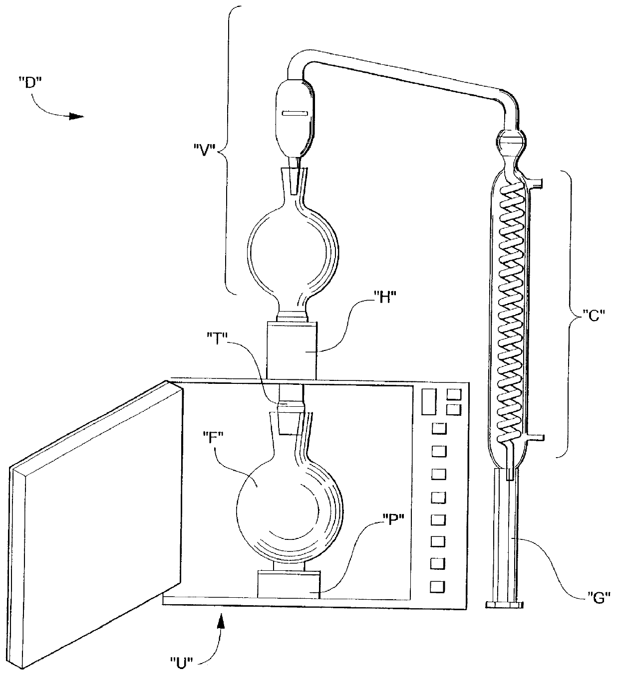
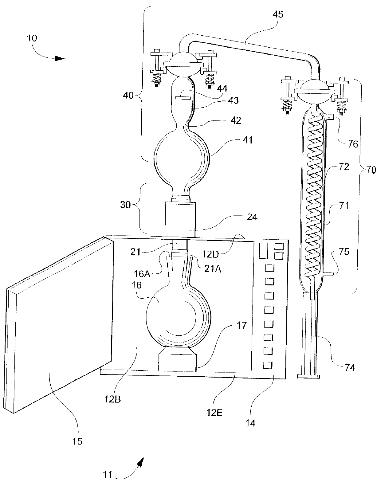
Referring now specifically to the drawings, a microwave distillation apparatus according to the present invention is illustrated in FIG. 3 and shown generally at reference numeral 10. The distillation apparatus 10 is suitable for quick and efficient distillation of beverages, such as citrus juices, using microwave energy. A previously described prior art embodiment of a distillation apparatus is shown in FIGS. 1 and 2.

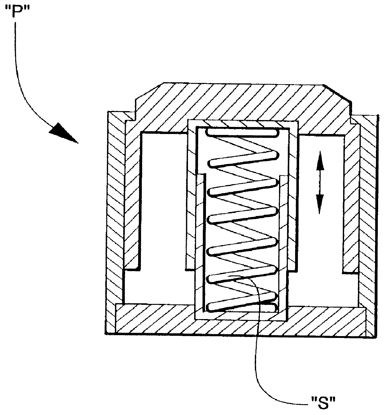
Referring to FIGS. 3 and 4, the present distillation apparatus 10 utilizes a microwave heating chamber 11, such as a conventional microwave unit or microwave oven with ceramic floor, biasing assembly 30, and a vapor transfer assembly 40 and condenser assembly 70 for capturing the liquid distillate. Each of these elements are discussed separately below.

Microwave Heating Chamber 11

The heating chamber 11 includes attached side walls 12A, 12B, 12C, top and bottom walls 12D and 12E, a microprocessor control panel 14, and an access door 15. A vessel 16 is located within the ...


PUM

PropertyMeasurementUnit
circumferenceaaaaaaaaaa
volatileaaaaaaaaaa
timeaaaaaaaaaa

Abstract

A microwave distillation apparatus is provided. The apparatus includes a microwave heating chamber having a plurality of walls. A vessel is located within the chamber for containing a liquid to be distilled. The vessel has a mouth for receiving the liquid. A connecting tube extends though an opening formed in one of the plurality of chamber walls. The connecting tube has a first end thereof for sealably engaging the mouth of the vessel, and a second end thereof extending outwardly from the chamber. A biasing assembly is located outside of the chamber, and engages the connecting tube with a biasing force to maintain the seal between the connecting tube and the mouth of the vessel. A distillate capture assembly is connected to the connecting tube for receiving vapors emitted from the liquid when heated, and for condensing the vapors into a liquid distillate for capture and storage.

Description

TECHNICAL FIELD AND BACKGROUND OF THE INVENTIONThis invention relates to a microwave distillation apparatus, and vessel-biasing assembly. The invention is applicable for quick and efficient distillation of beverages, such as citrus juices, using microwave energy. For example, a common practice in the juice industry includes extracting the juice from fresh fruit, removing a substantial portion of water from the juice to form a concentrate, shipping the concentrate to a processing and testing facility, and then returning a proper amount of water back into the concentrate before delivering the juice to a grocery store or other end user.A number of quality assurance tests are performed during rehydration of the juice concentrate, and before the juice is bottled and sold. One key test relates to the amount of volatile juice flavorings, or chemical compounds known as essence, present in the juice after shipment. This essence is generally obtained for testing through distillation.According...

Claims


Application Information

Patent Timeline
Patent Type & Authority Patents(United States)
IPC IPC(8): B01D5/00B01D1/00B01D3/00G01N1/44
CPCB01D1/0017B01D3/00B01D5/0063G01N1/44Y10S159/42Y10S203/02Y10S159/26Y10S203/11
Inventor ARMSTRONG, BERNARD
Owner ARMSTRONG BERNARD
Why Eureka
Try Eureka