Method for the acquisition of images by confocal microscopy

a confocal microscopy and image acquisition technology, applied in the field of confocal microscopy acquisition methods, can solve the problems of poor observability and inobservability of interested microscopical structures

Inactive Publication Date: 2000-01-18
CONSIGLIO NAT DELLE RICERCHE
View PDF6 Cites 42 Cited by
  • Summary
  • Abstract
  • Description
  • Claims
  • Application Information

AI Technical Summary

Problems solved by technology

When the structures to be analysed by a confocal method are in a relatively thick material and with light scattering properties, an increasing loss of contrast with the increase of the scattering occurs that may result in a poor observability or, in an extreme case, the inobservability of the interested microscopical structures.

Method used


Image

  • Method for the acquisition of images by confocal microscopy
  • Method for the acquisition of images by confocal microscopy
  • Method for the acquisition of images by confocal microscopy

Examples


Embodiment Construction

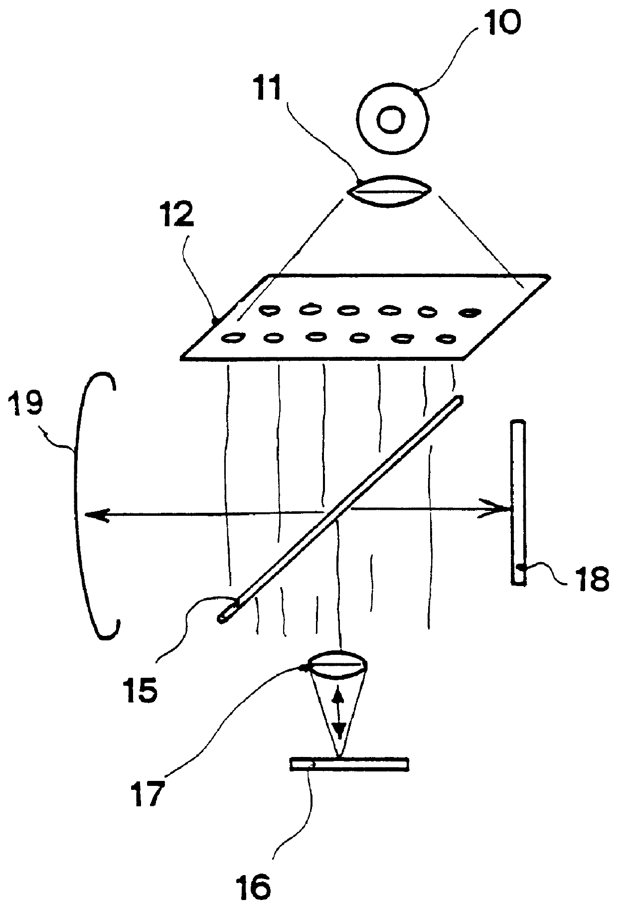
With reference to FIG. 1, the conventional general arrangement of a confocal microscope is shown herein. A light source 10 cooperates with a collimating lens 11, the output light beam of which passes through a hole matrix diaphragm 12 or equivalent device which is displaced according two coordinate axes x, y by means of motors, not shown, preferably by step motors. The structure formed by said hole matrix diaphragm can be replaced by a xy matrix scanning device formed by a liquid crystal light valve optoelectronic device and without moving mechanical parts. The light passing through hole matrix diaphragm 12 meets a beam divider 15. A part of the light crossing beam divider 15 is focused on a specimen 16 by means of a lens 17. The part of the light reflected at left of beam divider 15 is captured by a light trap 19 as well-known in these optical arrangements to eliminate back scattered disturbing light. The light returning from specimen 16 is directed to an image photoelectric sensor...


PUM


Abstract

A method for the acquisition of images by means of confocal microscopy in which a new image is calculated which is constituted by the "maxima" among the corresponding elements of each captured image. The new image contains mainly the signal coming from the most luminous and in focus areas and even the signal coming from the less luminous areas, as being out of focus or laterally displaced with respect to the grid positions. A further image is then calculated which is constituted by the "minima" among the corresponding elements of each captured image and the requested confocal image is then obtained by calculating the difference between the "maxima" image and the "minima" image.

Description

The present invention relates to a method for the acquisition of images by means of confocal microscopy.More particularly, the present invention relates to a method for the confocal images acquisition in optical systems for the analytical microscopy and in other optical systems with a relatively high numerical aperture involving the electronic images acquisition. The objects to be analysed can be absorbing (transmission), reflecting or fluorescent, and the optical arrangements can therefore vary among those for the analysis under transmitted or reflected light or under fluorescence.DESCRIPTION OF THE PRIOR ARTThe confocal microscopy, or anyway the analysis and the processing of images of objects by means of confocal systems with optical and electronical means, is a technique which grew considerably in recent years only. On this subject reference can be made to the article "Confocal Microscopy" by Jeff W. Lichtman, Scientific American, August 1994, as well as patent applications DE-A...

Claims


Application Information

Patent Timeline
Patent Type & Authority Patents(United States)
IPC IPC(8): G02B21/00G06T5/50
CPCG02B21/004G02B21/0056G02B21/0076G02B21/008G06T5/50
Inventor BENEDETTI, PIER ALBERTOEVANGELISTA, VALTEREGUIDARINI, DANTEVESTRI, STEFANO
Owner CONSIGLIO NAT DELLE RICERCHE
Why Eureka
Try Eureka