Counter for metal nano particles in solution

A metal nanoparticle and counter technology, applied in scientific instruments, individual particle analysis, particle and sedimentation analysis, etc., can solve the problems of large sample volume, limited application, low sensitivity, etc., achieve simple optical configuration, broad application prospects, Improve the effect of detection sensitivity

Inactive Publication Date: 2009-11-18
SHANGHAI JIAO TONG UNIV
View PDF0 Cites 9 Cited by
  • Summary
  • Abstract
  • Description
  • Claims
  • Application Information

AI Technical Summary

Problems solved by technology

The instruments used in these methods are simple, but their main disadvantages are that the detection sensitivity is not high, the required sample volume is relatively large, and their applications are very limited.

Method used


Image

  • Counter for metal nano particles in solution
  • Counter for metal nano particles in solution
  • Counter for metal nano particles in solution

Examples


Embodiment 1

[0030] Embodiment 1 gold nanoparticle counting analysis:

[0031] Laser: He-Ne laser (632.8 nm), dichroic mirror at 650 nm,

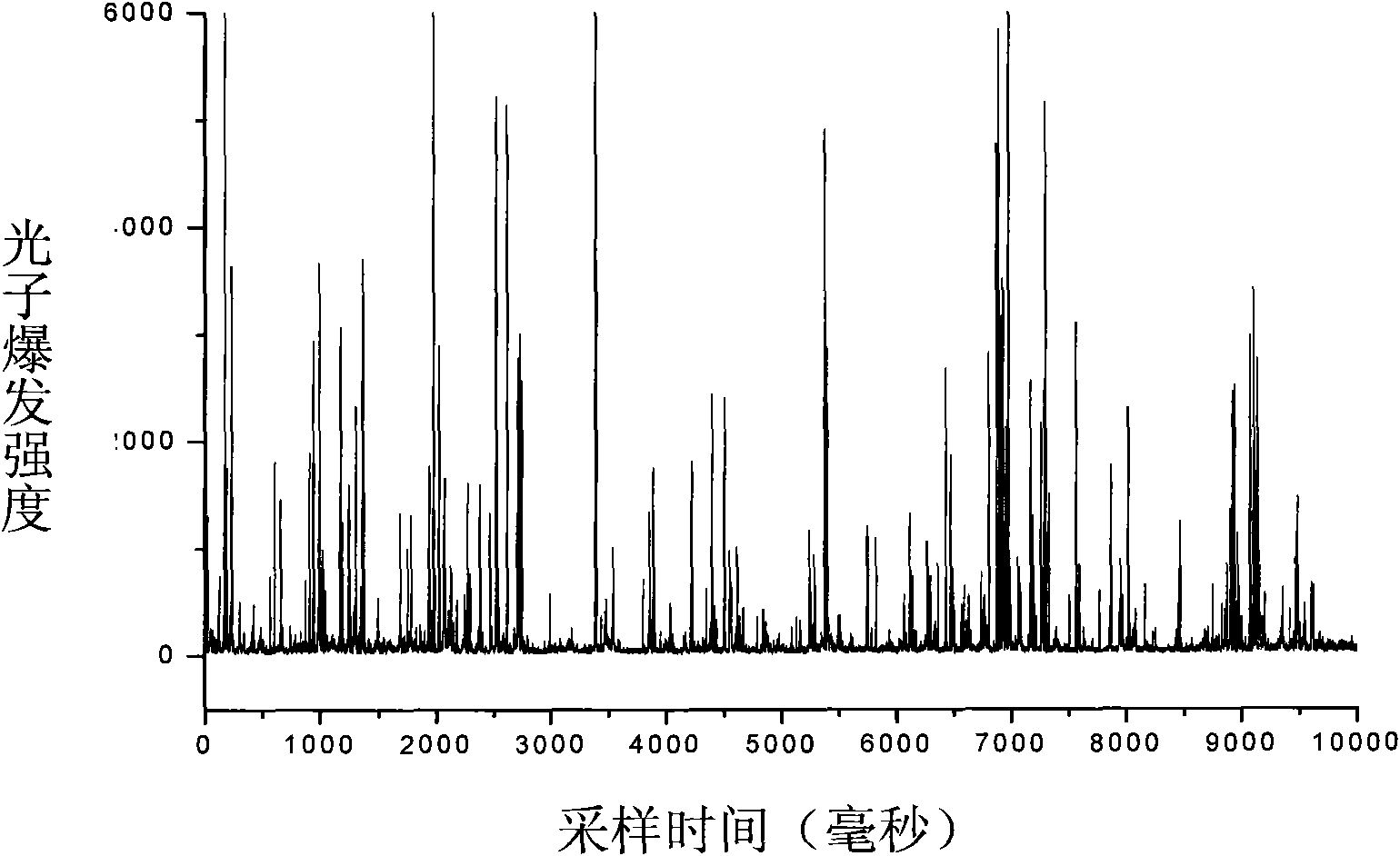
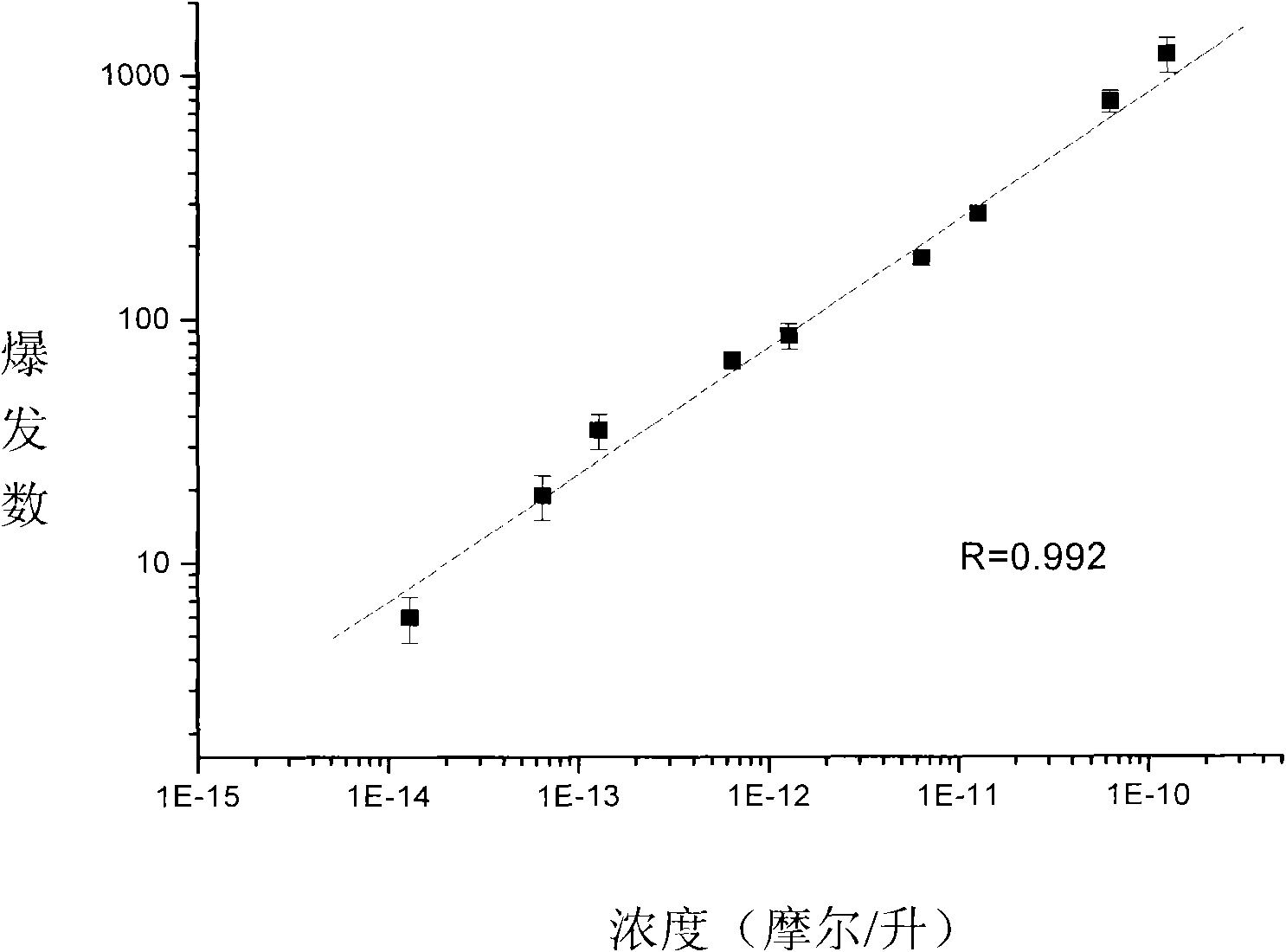
[0032] Using a 35 micron pinhole, the sample measurement process was as described above. figure 2 A photon burst diagram of gold nanoparticles is given. figure 2 The abscissa of is the recording time (or measurement time), the ordinate is the burst intensity of photons, and each peak represents a burst. image 3 is the linear relationship between the number of photon bursts and the concentration of gold nanoparticles. The abscissa is the concentration of gold nanoparticles, and the ordinate is the number of bursts of photons (that is, the number of peaks in the figure). The concentration of gold nanoparticles in the solution to be tested can be calculated according to the linear relationship between the number of photon bursts and the concentration of gold nanoparticles by measuring the number of luminescent gold nanoparticles in an unknown solutio...

Embodiment 2

[0033] Embodiment 2 Silver nanoparticles count analysis:

[0034]Laser: Argon ion laser (488 nm), dichroic mirror at 505 nm.

[0035] Using a 35 micron pinhole, the sample measurement process was as described above. Figure 4 A photon burst diagram of gold nanoparticles is given. Figure 5 Linear relationship between the number of photon bursts and the concentration of silver nanoparticles.

Embodiment 3

[0036] Embodiment 3 gold and silver nanoparticles count analysis

[0037] Laser: semiconductor laser (543 nm), dichroic mirror 550 nm.

[0038] Using a 35 micron pinhole, the sample measurement process was as described above. Figure 6 and Figure 7 The photon burst diagrams of silver nanoparticles and gold nanoparticles are given respectively.

[0039] It can be known from the above embodiments that the metal nanoparticle counter of the present invention can accurately and sensitively detect the photon burst of a single metal nanoparticle. At the same time, because the number of photon bursts of nanoparticles in the solution is proportional to the concentration of nanoparticles, the concentration of metal nanoparticles can be determined according to the number of photon bursts.


PUM

PropertyMeasurementUnit
diameteraaaaaaaaaa
particle diameteraaaaaaaaaa

Abstract

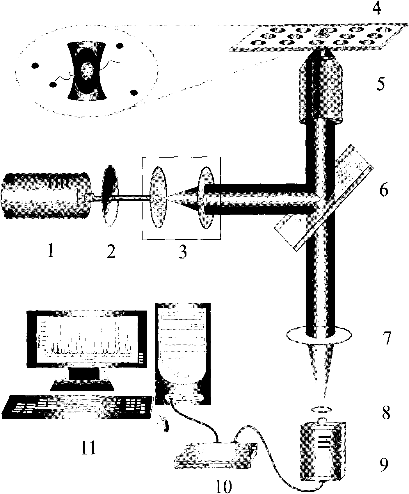
The invention relates to a counter for metal nano particles in solution, which is used for measuring relative concentration of metal nano particles in solution. The counter comprises a laser, a neutral attenuator, a beam expanding lens, a cover glass or a sample cell, a micro objective, a dichroic mirror, a lens, a pinhole, a single photon detector, a data collection card and a computer. Sample solution is placed on the cover glass or on the sample cell, the laser irradiates the metal nano particles in the solution, the produced scattered light is focused on the pinhole by the lens after being collected by the objective lens and the pinhole is coupled with the single photon detector. Signals generated by the single photon detector are output by the computer via the data collection card. The operating principle of the invention is based on a very small laser confocal irradiation micro-area (-10 litre), photon burst occurs when the metal particles enter or leave the micro-area due to Brownian movement, the number of the photon burst is proportional to concentration thereof. The counter of the invention can be applied to researches and clinical detection in fields such as biomedicine, chemistry, physics and the like.

Description

technical field [0001] The invention relates to a metal nanoparticle counter in a solution, which is used for measuring the relative concentration of the metal nanoparticle and can be widely used in nanoscience, life science, chemistry, physics and other technical fields. Background technique [0002] Certain metal (such as gold and silver) nanoparticles exhibit special optical properties, such as strong scattering and absorption properties, due to their surface plasmon effects and quantum size effects. At the same time, gold (silver) nanoparticles have the characteristics of good biocompatibility and easy connection with biomolecules, and are a kind of biological probes with broad application prospects. At present, gold nanoprobes have been successfully applied in the fields of nucleic acid hybridization detection, immunoassay and cell imaging. At present, the methods for detecting metal (such as gold) nanoparticles mainly include: colorimetric method, ultraviolet spectros...

Claims


Application Information

Patent Timeline
Patent Type & Authority Applications(China)
IPC IPC(8): G01N15/10
Inventor 任吉存谢超
Owner SHANGHAI JIAO TONG UNIV
Why Eureka
Try Eureka