Radiant electric heater

a technology of electric heater and rotary heater, which is applied in the direction of electric heating, ohmic-resistance heating, electrical apparatus, etc., can solve the problems of insufficient electric current level of contacts in standard thermal limiters and energy regulators, inability to provide a solution, and greater surface power loading over the inner zone than that over the outer zon

Inactive Publication Date: 2000-01-25
CERAMASPEED ACQUISITION COMPANY
View PDF10 Cites 26 Cited by
  • Summary
  • Abstract
  • Description
  • Claims
  • Application Information

AI Technical Summary

Benefits of technology

It is an object of the present invention to overcome or minimise these problems where three heating zones are present.

Problems solved by technology

Problems have been encountered with such heaters in that it is desirable when heating a small utensil on, for example, an inner heating zone of the heater, for the heating element in such inner zone to be energised with a power level comparable to a single zone heater of similar dimensions.
However when a larger utensil is being heated, covering both the inner zone and an annular heating zone surrounding the inner zone, then, when the heating element of the outer zone is energised in parallel with the element of the inner zone, the high power of the inner zone results in the surface power loading over the inner zone being greater than that over the outer zone which is disadvantageous.
A further problem is that with large multi-zone heaters, for example of the order of 300 mm diameter, provision of heating elements to provide a conventional surface power loading of, for example, about 7 watts per square centimeter results in an electric current level in excess of the handling capabilities of the contacts in standard thermal limiters and energy regulators used in the art.
Nevertheless, this does not provide a solution where more than two heating zones are present.

Method used


Image

  • Radiant electric heater
  • Radiant electric heater
  • Radiant electric heater

Examples


Embodiment Construction

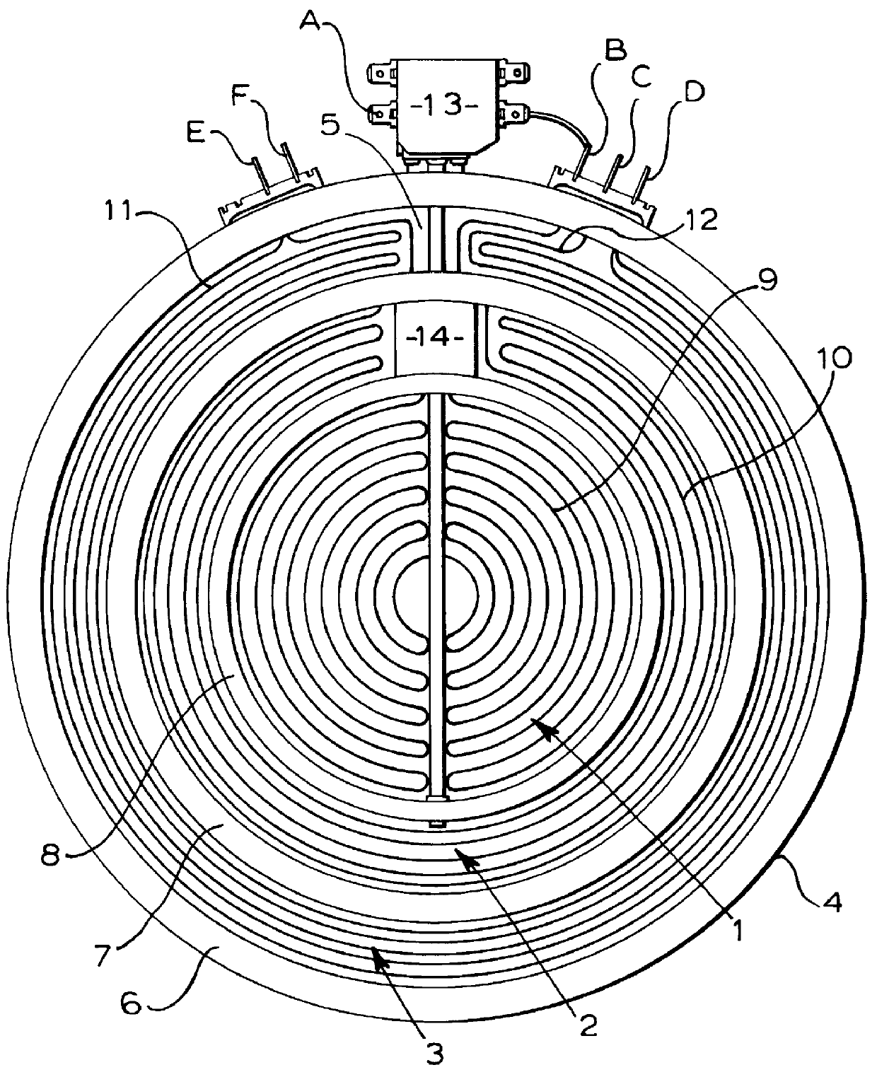
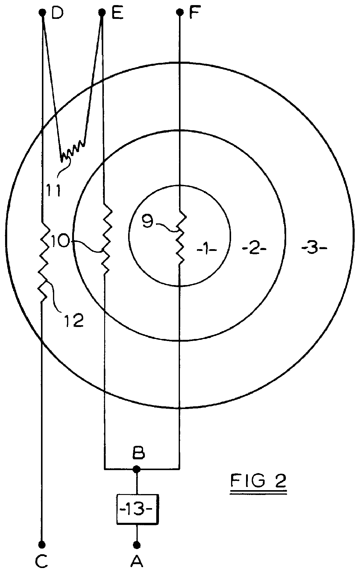
A radiant electric heater is constructed having three concentric heating zones 1, 2, 3. A circular first heating zone 1 is surrounded by an annular second heating zone 2 which is in turn surrounded by an annular third heating zone 3.

The three heating zones are formed as follows. A metal supporting dish 4 has provided therein a base layer 5 of insulation material, such as well known microporous thermal and electrical insulation material. A peripheral wall 6 of insulation material of well known form is provided around the edge of the dish and two further annular walls 7, 8 of similar form are provided in the dish to define the heating zones 1, 2 and 3. The heater is intended for use in a glass-ceramic cooking appliance with at least the peripheral wall 6 in contact with the underside of a glass-ceramic cooking surface (not shown).

A first heating element 9, which may be of ribbon form although any other forms could be considered, is provided in the first heating zone 1.

A second heating...


PUM


Abstract

A radiant electric heater has first, second and third heating zones (1, 2, 3) arranged substantially side-by-side. The first heating zone (1) is provided with at least one first heating element (9). The second heating zone (2) is arranged adjacent to the first heating zone and is provided with at least one second heating element (10). The third heating zone (3) is arranged adjacent to the second heating zone and is provided with at least one third and one fourth heating element (11, 12). A switch (15) is provided for switching between first, second and third heating states. In the first heating state the at least one first heating element (9) of the first heating zone (1) is energised alone, the at least one second, third and fourth heating elements (10, 11, 12) of the second and third heating zones (2, 3) being de-energised. In the second heating state the at least one first heating element (9) of the first heating zone (1) is electrically connected and energised in parallel with the at least one second heating element (10) of the second heating zone (2), the at least one third and fourth heating elements (11, 12) of the third heating zone (3) being de-energised.

Description

This invention relates to a radiant electric heater having multiple heating zones and which may be used, for example, in a cooking appliance having a glass-ceramic cooking plate. More particularly the invention relates to such a heater having three heating zones, which may be concentrically arranged, and particularly, although not exclusively, to such a heater having relatively large overall diameter, for example of the order of 300 mm.DESCRIPTION OF PRIOR ARTRadiant heaters having multiple, particularly two, concentric heating zones are well known for use in glass-ceramic cooking appliances.U.S. Pat. No. 4,158,127 describes a range top having a plurality of main cooking stations with an auxiliary cooking station disposed in the vicinity of at least one of the main cooking stations and being conformed to and contiguous with the main cooking station to define a substantially continuous enlarged cooking area. A further auxiliary cooking station may be disposed between adjacent main co...

Claims


Application Information

Patent Timeline
Patent Type & Authority Patents(United States)
IPC IPC(8): H05B1/02H05B3/68H05B3/74
CPCH05B1/0266H05B3/74
Inventor HIGGINS, GEORGE ANTHONY
Owner CERAMASPEED ACQUISITION COMPANY
Why Eureka
Try Eureka