Antennas with integrated windings

a technology of integrated windings and antennas, which is applied in the direction of collapsible antenna means, non-resonant long antennas, waveguide types, etc., can solve the problems of complex mechanical and electrical connections, complicated design restraints on the antenna, and laborious fabrication of flexible antenna elements, etc., to achieve convenient use, reliable, durable and economical

Inactive Publication Date: 2000-01-25
BLACKBERRY LTD
View PDF15 Cites 33 Cited by
  • Summary
  • Abstract
  • Description
  • Claims
  • Application Information

AI Technical Summary

Benefits of technology

It is yet another object of the present invention to provide a reliable, durable, and economical satellite antenna for a radiotelephone.
It is a further object of the present invention to provide an improved antenna which can be conveniently adapted for use with existing radiotelephone models.

Problems solved by technology

Additionally, many of the radiotelephones are undergoing miniaturization which can complicate and impose design restraints on the antenna.
For example, this miniaturization can create complex mechanical and electrical connections with other components such as the outwardly extending antenna which must generally interconnect with the housing for mechanical support, and, to the signal processor and other internal circuitry operably associated with the printed circuit board in the radiotelephone body.
Unfortunately, fabrication of these flexible antenna elements are typically relatively fragile and can be labor intensive.
Further, the positional tolerances of the elements relative to both the antenna cover or "radome" and the roll can be difficult to control.
Positional and form variance and the seam construction of the flex windings can undesirably affect the performance of the antenna.

Method used


Image

  • Antennas with integrated windings
  • Antennas with integrated windings
  • Antennas with integrated windings

Examples


Embodiment Construction

The present invention will now be described more fully hereinafter with reference to the accompanying figures, in which preferred embodiments of the invention are shown. This invention may, however, be embodied in many different forms and should not be construed as limited to the embodiments set forth herein. Like numbers refer to like elements throughout. Layers may be exaggerated for clarity. As used herein, rigid is meant to include windings or traces which are sufficiently inflexible such that they are static, i.e., such that they are fixed along an expanse of the (antenna) body.

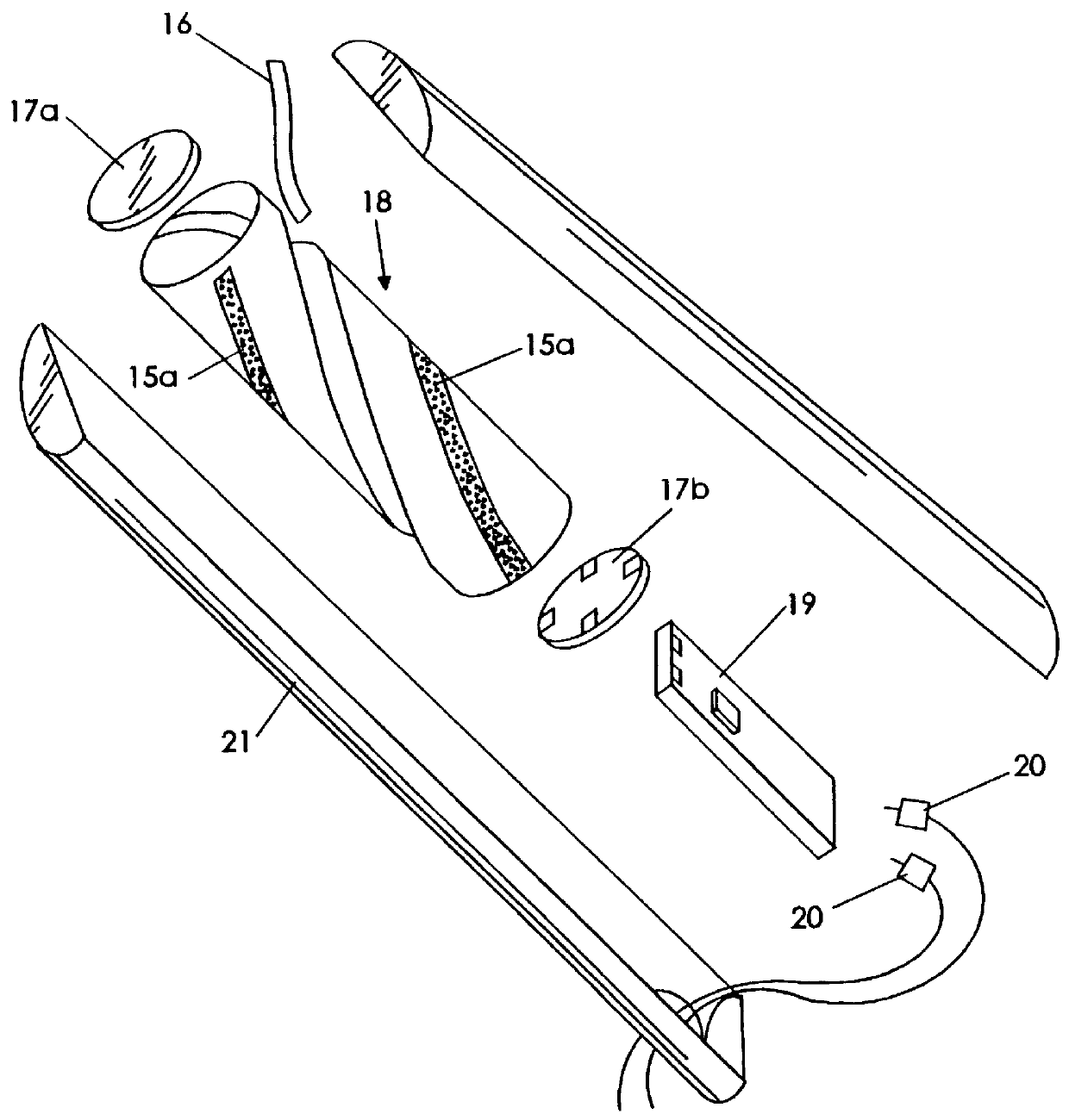
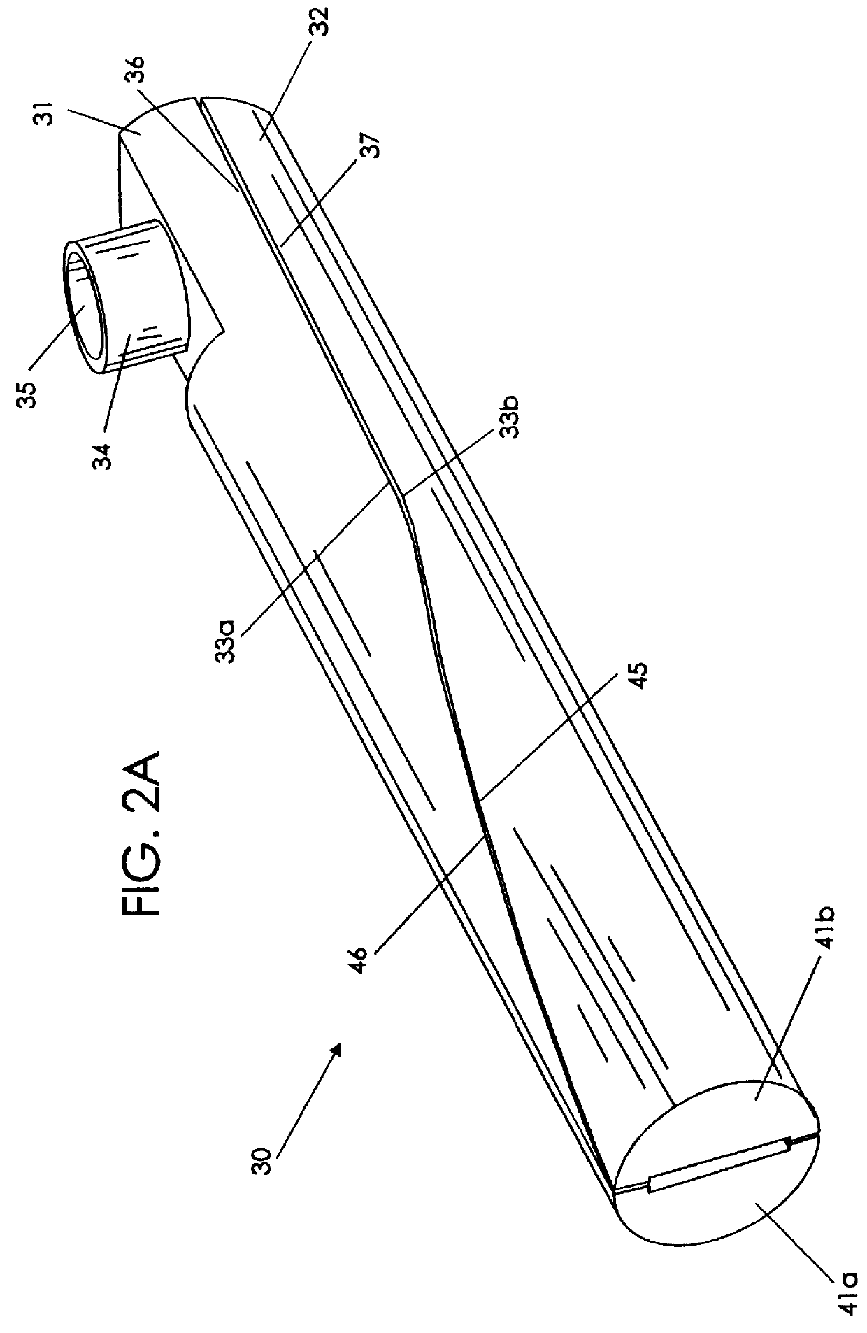
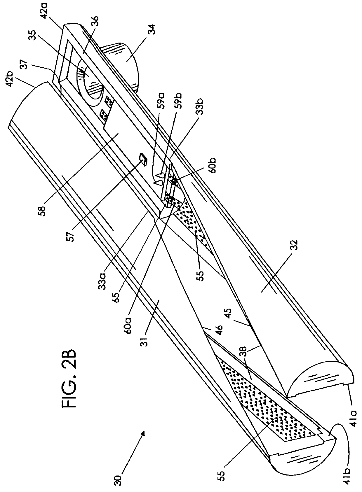
The present invention is directed towards antennas and is especially advantageous for antennas used in portable radiotelephone applications. Generally described, the present invention integrally forms the antenna element(s) directly into the antenna housing. This advantageously eliminates the wrapping or forming and assembly procedures of conventional flex circuit wrapped antennas as described above by p...


PUM

PropertyMeasurementUnit
conductiveaaaaaaaaaa
lengthaaaaaaaaaa
inner diameteraaaaaaaaaa

Abstract

Radiotelephone antennas include rigid antenna elements integral to the antenna substrate or housing. As such, the present invention configures the antenna without requiring a separate flex circuit winding to provide the conductive windings in the antenna. Methods for fabrication of the antenna are also described. Preferably, the antenna is formed in a two-shot molding process.

Description

The present invention relates to telephones, and more particularly relates to antennas in telephones.Many telephones employ antennas which are electrically connected to a signal processor housed in the telephone. Various design parameters of the antenna can affect the performance of the radiotelephone. For example, the size and shape of the antenna as well as the way in which the electrical traces of the antenna are interconnected with associated circuitry can impact the performance of the radiotelephone. Additionally, many of the radiotelephones are undergoing miniaturization which can complicate and impose design restraints on the antenna. For example, this miniaturization can create complex mechanical and electrical connections with other components such as the outwardly extending antenna which must generally interconnect with the housing for mechanical support, and, to the signal processor and other internal circuitry operably associated with the printed circuit board in the rad...

Claims


Application Information

Patent Timeline
Patent Type & Authority Patents(United States)
IPC IPC(8): H01Q1/36H01Q11/08H01Q1/38H01Q11/00H01Q1/24H01Q1/08
CPCH01Q1/084H01Q1/242H01Q1/36H01Q1/362H01Q11/08H01Q11/083H01Q11/086H01Q1/38Y10T29/49016H01Q1/24
Inventor RUDISILL, CHARLES A.
Owner BLACKBERRY LTD
Why Eureka
Try Eureka