Process and assembly for eliminating nitrogen oxides present in exhaust gas, using nitrogen oxides trapping means

a technology of nitrogen oxides and assembly means, which is applied in the direction of separation processes, machines/engines, mechanical apparatus, etc., can solve the problems of lack of nitrogen oxide conversion and ineffective nitrogen oxide conversion, and achieve the effect of limiting energy consumption

Inactive Publication Date: 2000-02-01
INST FR DU PETROLE
View PDF19 Cites 31 Cited by
  • Summary
  • Abstract
  • Description
  • Claims
  • Application Information

AI Technical Summary

Benefits of technology

According to another embodiment of the invention, the adsorbed NO.sub.x are desorbed by heating them with a specific heating means associated with said nitrogen oxides trapping means. Opening of the valve thus defines the optimum amount of gaseous stream to be heated, which notably allows to limit the energy consumed by the heating means.

Problems solved by technology

However, in this context, a problem comes up when the exhaust gas is not, at the level of the catalyst(s), within a temperature range for which conversion of the nitrogen oxides is sufficient.
More precisely, a problem comes up when a first catalyst is active in a first temperature range and a second catalyst is active in a second temperature range, and when these ranges are such that there is a range of temperatures between and above the two temperature ranges defined above in which the nitrogen oxides conversion will be low.
Furthermore, at the lowest temperatures, i.e. before the gas reaches a temperature where it is likely to be converted by one of the catalysts, there is also a lack of nitrogen oxides conversion.
It is of course obvious that, between these two ranges, i.e. here between 250.degree. C. and 300.degree. C., no nitrogen oxides conversion can be performed effectively.

Method used


Image

  • Process and assembly for eliminating nitrogen oxides present in exhaust gas, using nitrogen oxides trapping means
  • Process and assembly for eliminating nitrogen oxides present in exhaust gas, using nitrogen oxides trapping means
  • Process and assembly for eliminating nitrogen oxides present in exhaust gas, using nitrogen oxides trapping means

Examples


Embodiment Construction

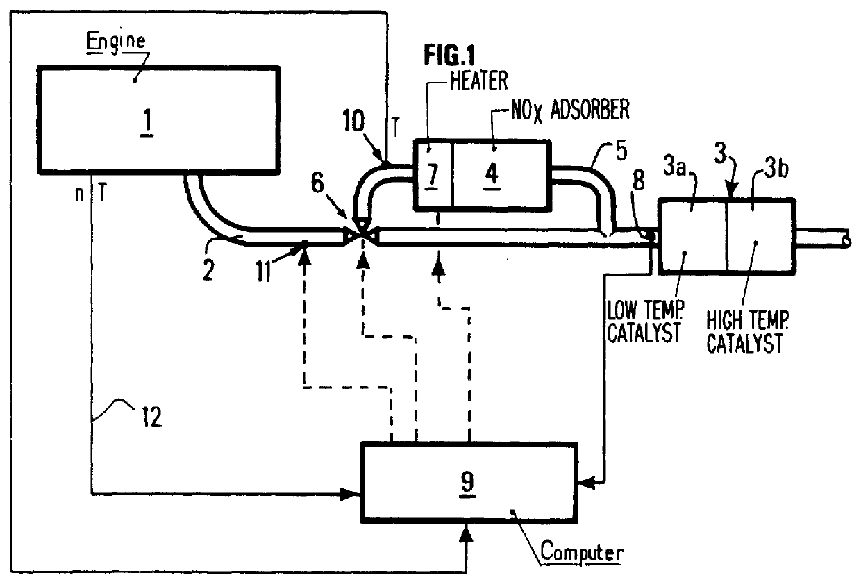
FIG. 1 illustrates the main structural elements forming the nitrogen oxides elimination assembly according to the invention.

An engine 1 is schematized with its main exhaust line 2, in which the invention is implemented.

The invention relates for example to lean-burn diesel or spark-ignition engines for which NO.sub.x reduction is difficult.

One or more DeNO.sub.x catalysts 3, e.g., 3a, 3b, are placed on exhaust line 2 as it is known in the art. According to the formulation thereof, each catalyst acts for a specific exhaust gas temperature range.

Furthermore, a nitrogen oxides trapping means 4 can be added in exhaust line 2.

According to the invention, at least one line 5 bypassing main exhaust line 2 is provided, and at least one nitrogen oxides trapping means 4 (NO.sub.x adsorber) is placed in line 5.

Bypass line 5 opens into main line 2 just upstream from DeNO.sub.x catalysts 3.

Furthermore, a throttling means 6 is provided at the intersection of main line 2 and bypass line 5, on the up...


PUM

PropertyMeasurementUnit
temperaturesaaaaaaaaaa
temperatureaaaaaaaaaa

Abstract

A process and an assembly for eliminating nitrogen oxides (NO.sub.x) present in the exhaust gas of a lean-burn diesel or spark-ignition engine, is part of the exhaust line coming from the engine. At least one nitrogen oxides conversion catalyst is placed in the main exhaust line the catalysts having non-coinciding temperature ranges for which the NO.sub.x conversion is below a certain conversion coefficient (C.sub.min). At least one NO.sub.x trap placed upstream is the conversion catalyst(s) and intended to trap, then to release the nitrogen oxides. At least one line bypassing the main exhaust line contains at least one of the NO.sub.x trap(s); and at least one valve intended to modulate the flow of gas between the bypass line and the main exhaust line is provided so that the NO.sub.x trap(s) can trap the nitrogen oxides, notably when conversion catalyst(s) have a conversion coefficient below a predetermined value (C.sub.min) and so that said the NO.sub.x trap(s) means (4) can release the nitrogen oxides simultaneously with a conversion.

Description

FIELD OF THE INVENTIONThe present invention relates to the processing of gas discharged at the exhaust of lean-burn diesel and spark-ignition engines.Such engines emit a certain number of pollutants that have to be eliminated, which must be done all the more effectively because standards become increasingly stringent.Examples of the most numerous pollutants which have the most harmful effects on the environment are nitrogen oxides.BACKGROUND OF THE INVENTIONIt is well-known to eliminate this type of pollutants by passing the exhaust gas through catalysts (referred to as DeNO.sub.x catalysts) intended for nitrogen oxides conversion. The known catalysts being active within a given temperature range, several catalysts having different formulations, i.e. different activity ranges, may be placed in the catalytic muffler. The sphere of action of the catalytic elements is thus extended. However, in this context, a problem comes up when the exhaust gas is not, at the level of the catalyst(s...

Claims


Application Information

Patent Timeline
Patent Type & Authority Patents(United States)
IPC IPC(8): B01D53/94F01N3/08F02B1/04F02B1/00F01N3/20F01N3/24F01N3/28
CPCB01D53/9481B01D53/9495F01N3/0842F01N3/0878B01D53/9409B01D2251/208B01D2258/012F01N2250/12F02B1/04Y02T10/24Y02T10/12
Inventor MARTIN, BRIGITTEBOUCHEZ, MATTHIAS
Owner INST FR DU PETROLE
Why Eureka
Try Eureka