Method for driving a plasma display panel

a plasma display and plasma technology, applied in the direction of instruments, optical light guides, optics, etc., can solve the problems of deterioration of the layer, lack of operation stability, and drop in luminan

Inactive Publication Date: 2000-02-01
MAXELL HLDG LTD +1
View PDF10 Cites 130 Cited by
  • Summary
  • Abstract
  • Description
  • Claims
  • Application Information

AI Technical Summary

Problems solved by technology

For this reason, the opposition discharge PDPs have some disadvantages: They lack stability in operation; the fluorescent layer deteriorates in a short time due to ion impact during discharges and thereby the luminance drops, and the like.
Accordingly, a priming effect of discharge cannot be utilized, and therefore a high writing voltage is required.
For this reason, there is a limit to high-speed drive for high-definition display.
Further, a driver of high voltage resistance is ...

Method used


Image

  • Method for driving a plasma display panel
  • Method for driving a plasma display panel
  • Method for driving a plasma display panel

Examples


first embodiment

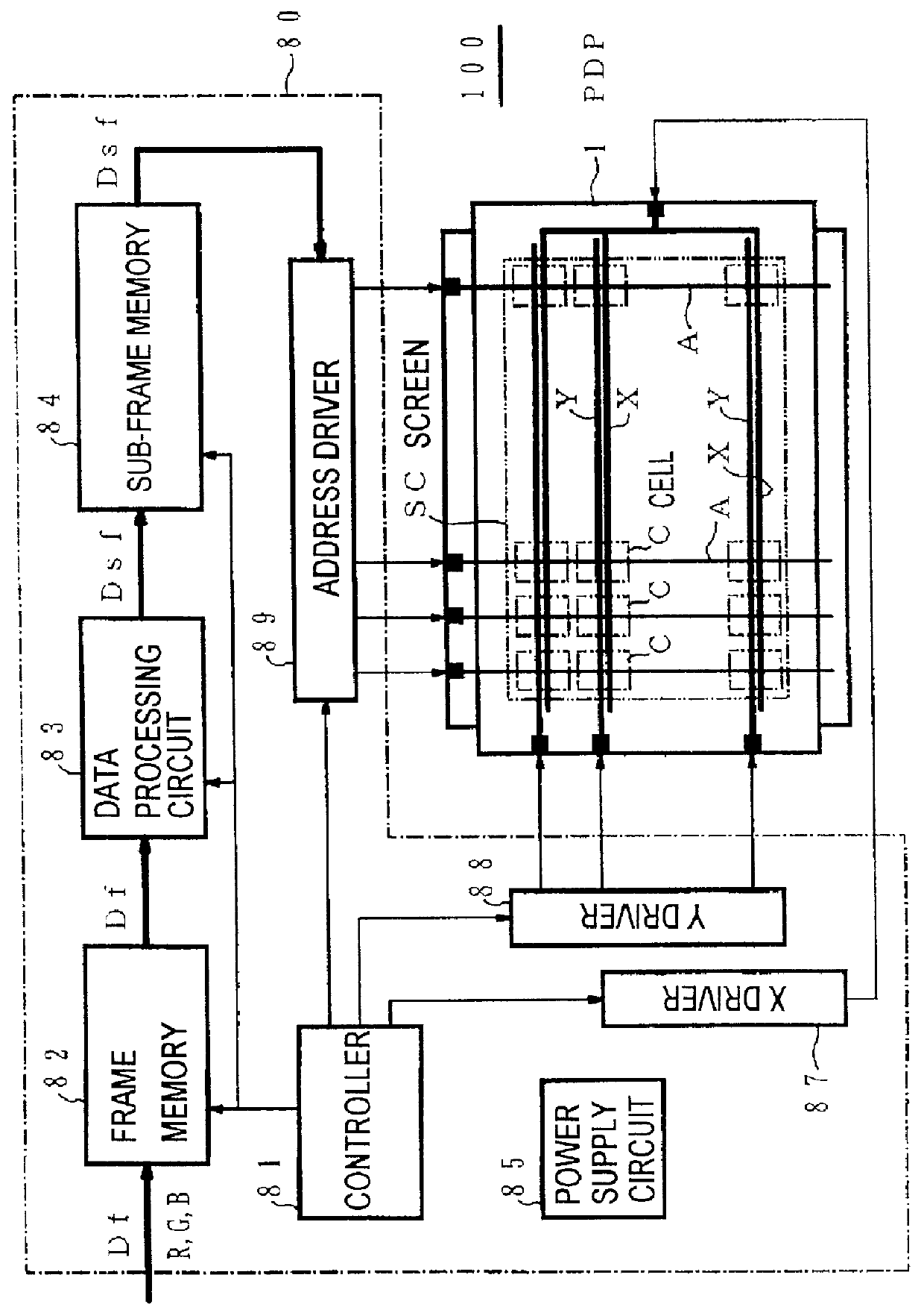
FIG. 1 a diagram illustrating the structure of a plasma display 100 in accordance with the present invention.

The plasma display 100 includes an AC-driven PDP 1 which is a color display device of matrix system and a drive unit 80 for selectively lighting a large number of cells (i.e., discharge cells) C composing a screen SC. The plasma display 100 can be used as a wall-mountable television display or a monitor of a computer system.

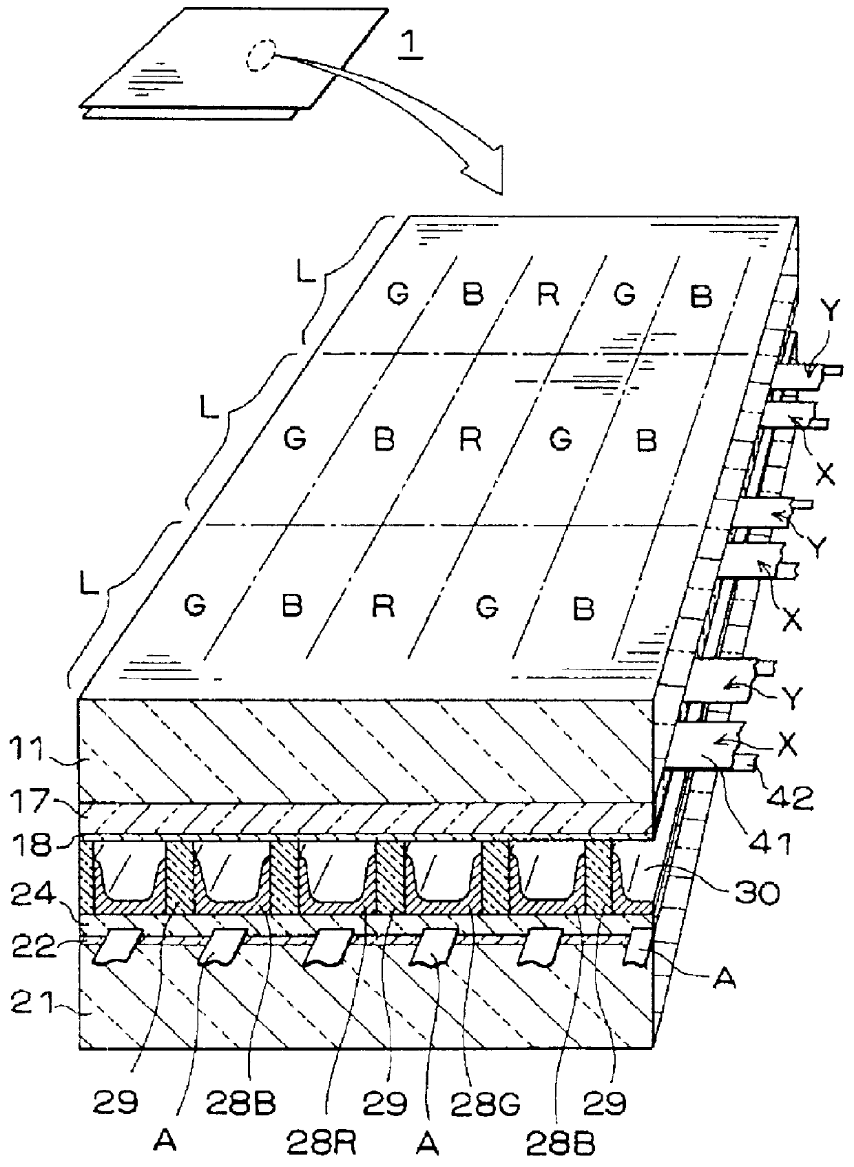
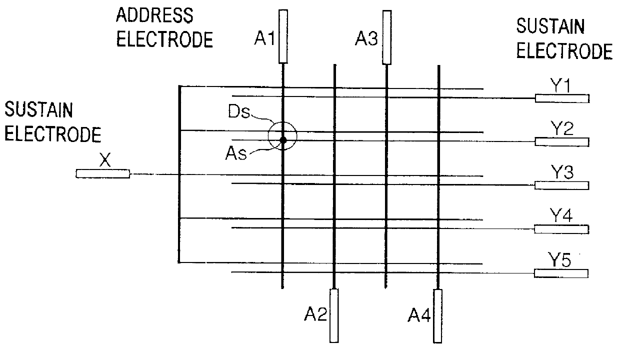
The PDP 1 is a three-electrode surface discharge PDP in which pairs of sustain electrodes X and Y are disposed in parallel as the first and second main electrodes and define cells as display elements at intersections with address electrodes A as the third electrodes. The sustain electrodes X and Y extend in the direction of rows, i.e., in a horizontal direction, on the screen. The sustain electrodes Y are used as scanning electrodes for selecting cells row by row in addressing. The address electrodes A extend in the direction of columns, i.e., in a vertica...

second embodiment

In the display of images by the above-described PDP, there exists a substantial hold period between the end of the sustain period for a certain image and the initialization period for the next image in time-sequential display of images with regular renewal. The hold period inevitably occurs when gradation display is performed with high fidelity to inputted imaged by a binary control on lighting. Normally, the hold period is equally assigned to each sub-frame (sub-field). The sum of the total hold periods is about 3 to 4 ms for an ordinary frame period of about 16.6 ms. A quiescent period of about several ten .mu.s is sometimes required for resetting a logic circuit for driving in every sub-frame.

This hold period is unpreferable in the case of the erase address method. The reason is that the amount of remaining wall charge decreases during the hold period, and therefore the discharge probability at the initialization period becomes smaller than that at the sustain period. As a result...

third embodiment

In the above-described First and Second Embodiments, however, even though the wall charge in the cells which need not emit light is normally erased, there are cases where space charge produced by the discharge for erasure remains excessively. In such cases, when the sustain pulse is applied, the priming effect of the space charge cause a discharge in the cells which need not emit light (mis-lighting). As a result, the wall charge is re-produced.

In this embodiment, described is a driving method for the PDP which allows prevention of such mis-lighting and realization of high-quality display free of flicker. In brief, Third Embodiment is partially improved First and Second Embodiments.

In this embodiment, the discharge probability is lowered at the beginning of the sustain period within such a range that failure in lighting does not occur, compared with that in the succeeding stages of the sustain period. Thereby, the discharge does not happen in non-selected cells which does not have a...


PUM


Abstract

A method for driving a plasma display panel includes carrying out an erase address operation when a display on the screen is renewed. The erase address operation includes the steps of carrying out an address preparation operation for producing the wall charge in all the discharge cells through a first step of generating a discharge only in a discharge cell in an ON-state and a second step of generating a discharge only in a discharge cell in an OFF-state, and carrying out an operation for selectively erasing the wall charge in a discharge cell other than a discharge cell corresponding to data of the image to be displayed.

Description

CROSS-REFERENCES TO RELATED APPLICATIONSThis application is related to Japanese applications Nos. HEI 9(1997)-065094 and HEI 9(1997)-233561, filed on Mar. 18, 1997 and Aug. 29, 1997 whose priorities are claimed under 35 USC .sctn.119, the disclosures of which are incorporated by reference in their entirety.1. Field of the InventionThe present invention relates to a method for driving plasma display panels (PDPs) which are used as display terminals for television sets and computers.2. Description of Related ArtIn recent years, the PDPs have been attracting much attention as large-sized flat displays capable of TV display in full color as their upsizing and adaptation to color display have been in progress. The PDPs are thought to be potential wall-mountable TV displays. For realizing such large-sized wall-mountable television displays, the PDPs are required to be further upsized, to provide images with higher definition, and also to exhibit a long-term stability in operation.In gener...

Claims


Application Information

Patent Timeline
IPC IPC(8): G09G3/28G09G3/20G09G3/292G09G3/293G09G3/294
CPCG09G3/2022G09G3/2927G09G3/2935G09G3/294G09G2310/065G09G2310/066G09G2320/0228
Inventor HIRAKAWA, HITOSHIKONDO, NOBUYOSHIOTSUKA, AKIRAKATAYAMA, TAKASHIKUROGI, SEIKINAKAHARA, HIROYUKI
Owner MAXELL HLDG LTD
Why Eureka
Try Eureka