Custom-fitted ankle splint

a custom-fitted, ankle splint technology, applied in the field of custom-fitted ankle splints, can solve the problems of inability to adjust the lengthwise of the splint by shortening or lengthening the heel support, reducing the effectiveness of the protection offered by the pad, and causing edema

Inactive Publication Date: 2000-02-08
BSN MEDICAL INC
View PDF8 Cites 24 Cited by
  • Summary
  • Abstract
  • Description
  • Claims
  • Application Information

AI Technical Summary

Benefits of technology

It is another object of the invention to provide an ankle splint which is custom-molded to a patient's ankle in such a way that it can be initially held in place with an elastic bandage to reduce edema on the front of the foot, and thereafter held in place with straps during later stages of healing.
It is another object of the invention to provide an ankle splint which includes reinforced cushioning and protection for the ankle bones of the patient.
These and other objects of the present invention are achieved in the preferred embodiments disclosed below by providing an ankle splint product including an ankle splint for being custom-formed to the shape of an ankle while flexible and upon hardening providing a rigid, supporting custom fit. The ankle splint product includes an outer container formed of moisture-impervious material and first and second flexible ankle splint segments positioned in the container in substantially moisture-free conditions and sealed therein against entry of moisture until use. Each of the first and second ankle s

Problems solved by technology

These products require a source of heat, and are susceptible to either over-or-underheating.
In addition, body heat itself can soften or increase the flexibility of the pad, thereby decreasing the effectiveness of the protection offered

Method used


Image

  • Custom-fitted ankle splint
  • Custom-fitted ankle splint
  • Custom-fitted ankle splint

Examples


Embodiment Construction

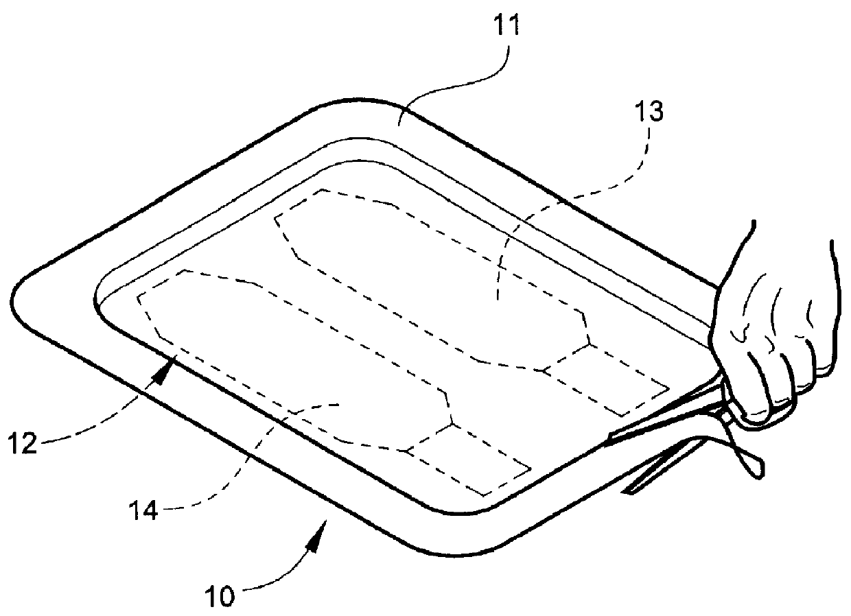
Referring now specifically to the drawings, an ankle splint product according to a preferred embodiment of the invention is illustrated broadly at reference numeral 10. A sealed, moisture-impervious foil and plastic laminated pouch or container 11 is fabricated of a aluminum foil laminate having an outer tear resistant layer, a central aluminum foil layer and an inner heat sealable plastic layer. Container 11 is opened with scissors or a knife, and an ankle splint 12 according to an embodiment of the invention is removed.

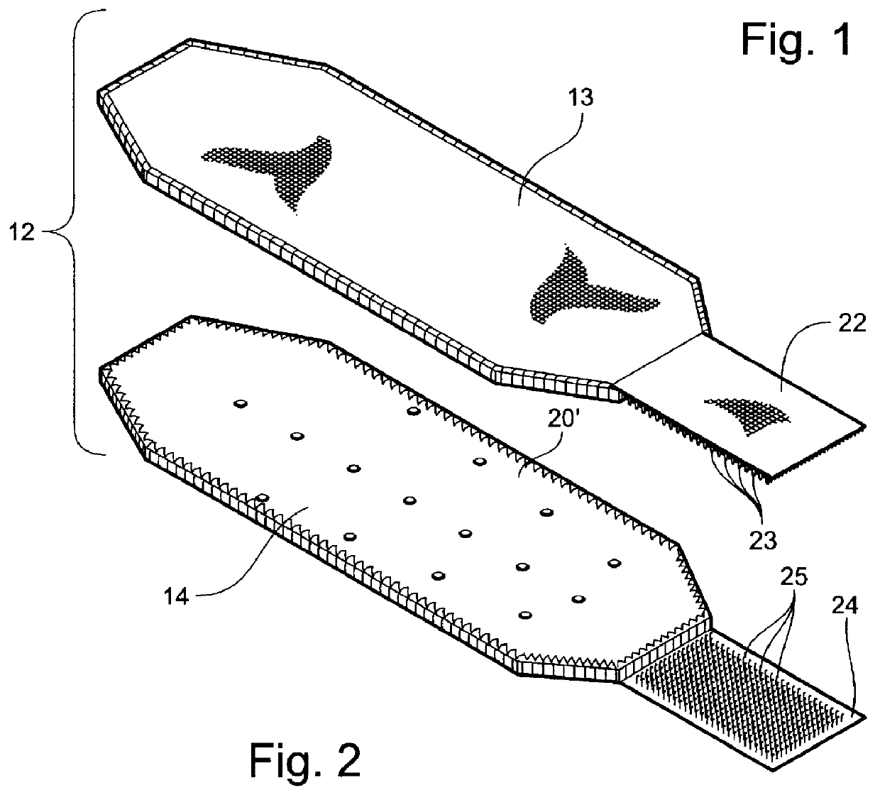
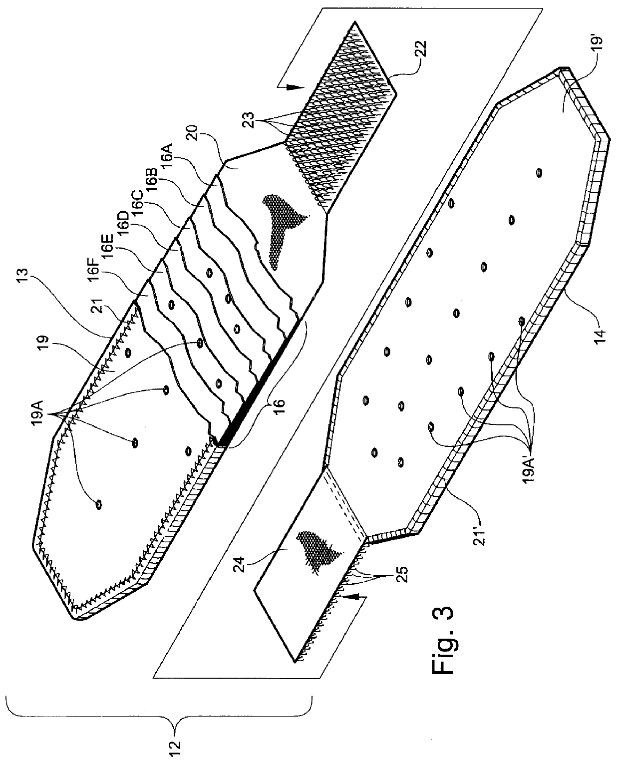
Ankle splint 12 is formed from first and second separate splint segments 13 and 14, as is shown in FIG. 2. Either of the splint segments 13 or 14 may be formed to the lateral or medial aspect of the ankle and lower leg. This interchangeability reduces manufacturing expense, inventory expense and simplifies application and replacement on the ankle after removal.

While it is preferable to place a splint segment 13 and 14 into a single container 11, each individual spli...


PUM


Abstract

An ankle splint product includes an ankle splint for being custom-formed to the shape of an ankle while flexible and upon hardening providing a rigid, supporting custom fit. The ankle splint product includes an outer container formed of moisture-impervious material, and first and second flexible ankle splint segments positioned in the container in substantially moisture-free conditions and sealed therein against entry of moisture until use. Each of the first and second ankle splint segments includes an elongate substrate and a reactive system impregnated into or coated onto the substrate. The system remains stable when maintained in substantially moisture-free conditions and hardens upon exposure to moisture to form a rigid, self supporting structure. An elongate, flexible protective pad is positioned on one side of the substrate along its length to provide a cushioning barrier between the substrate and the skin of a patient when the ankle splint is in use. An elongate outer cover covers the substrate on the side opposite the protective pad. A flexible cushion insert has a first major surface overlying the protective pad and an opposing second major surface adapted for residing adjacent an ankle bone of the patient. The cushion insert cooperates with the protective pad to further protect and cushion the ankle of the patient when the ankle splint is in use.

Description

TECHNICAL FIELD AND BACKGROUND OF THE INVENTIONThis invention relates to a custom-fitted ankle splint.The invention has particular application in the orthopedic medical field, where ankle sprains or fractures are often supported and immobilized with a splint or brace so that the patient can continue to walk while the injury heals. One typical such injury is a sprain of the anterior talofibular ligament at the interior margin of the lateral malleolus. In such cases, it is essential to splint the ankle in such a way as to stabilize the ankle against eversion and inversion while permitting dorsiflexion and planoflexion necessary for normal walking and therapeutic exercise. It is also desirable for the splint to be sufficiently compact to fit within a conventional shoe. This facilitates sufficient use of the injured ankle during healing so that muscle atrophy is avoided or minimized.The invention takes advantage of polymer chemistry to permit quick and easy molding of a splint to the an...

Claims


Application Information

Patent Timeline
IPC IPC(8): A61F5/01A61F5/02
CPCA61F5/0111
Inventor DARCEY, THOMAS D.
Owner BSN MEDICAL INC
Why Eureka
Try Eureka