
Injector air outlet with a sensor for temperature and smoke monitoring

a technology of temperature and smoke monitoring and injector air outlet, which is applied in the direction of alarms, fire alarms, instruments, etc., can solve the problems of measurement error or triggering delay in the functioning of smoke detectors or alarms, and the deviation between the measured temperature of the freight compartment and the actual or true representative interior temperature of the overall freight compartmen

Inactive Publication Date: 2000-02-15
DAIMLER CHRYSLER AEROSPACE AIRBUS +1
View PDF6 Cites 46 Cited by
  • Summary
  • Abstract
  • Description
  • Claims
  • Application Information

AI Technical Summary

Benefits of technology

to provide an injector air outlet of the above mentioned general type which is embodied and adapted to constantly monitor the temperature and smoke content of room air sucked out of a closed space within the fuselage of an aircraft. It is a further object of the invention to provide such an injector air outlet that incorporates components for continuously determining the temperature and / or smoke content of the air and providing corresponding monitoring signals to further processing equipment, whereby the monitoring is subject to the smallest possible measuring errors or deviations. Furthermore, the injector air outlet should be capable of blowing a jet or flow of air into the enclosed space within the fuselage so as to influence the air flow pattern of the room air in such a manner so as to achieve a thorough mixing of the room air and simultaneously prevent a temperature stratification of the room air in order to achieve a homogeneous distribution of the room air that is to be sucked into the injector air outlet, independently of the layout or loading configuration of the space. Consequently, the temperature regulation as well as the triggering characteristic of the smoke detection and smoke alarm for closed spaces within the fuselage of an aircraft are to be improved in comparison to the prior art. The invention further aims to avoid or overcome the disadvantages of the prior art, and to achieve additional advantages, as apparent from the present description.

Problems solved by technology

However, in actual practice, varying loading configurations of different freight items within the freight compartment in successive flights lead to varying spatial air flow patterns through the freight compartment, which in turn cause considerable deviations between the measured freight compartment temperature and the actual or true representative interior temperature of the overall freight compartment.
Since the spatial air flow pattern through the freight compartment will vary dependent upon the varying loading configurations, as described above, the functioning of the smoke detectors or alarms is also subject to a measurement error or triggering delay that is dependent upon the particular loading configuration at any given time.
There is no known solution or suggestion for overcoming the above described problems involved in the constant monitoring of the temperature and of the possible presence of smoke in the air within closed spaces or compartments in the fuselage of an aircraft, and particularly the freight compartments.
Especially, the known art provides no suggestions for minimizing or achieving the smallest possible measurement errors or variations, of which the monitoring results are completely or substantially independent of the particular loading configuration or cabin layout and passenger loading in the freight or passenger compartments of an aircraft.
Moreover, the prior art has not provided any manner of increasing the reliability of the temperature regulation and smoke detection in such freight and / or passenger compartments in an aircraft.

Method used


Image

  • Injector air outlet with a sensor for temperature and smoke monitoring

Examples


Embodiment Construction

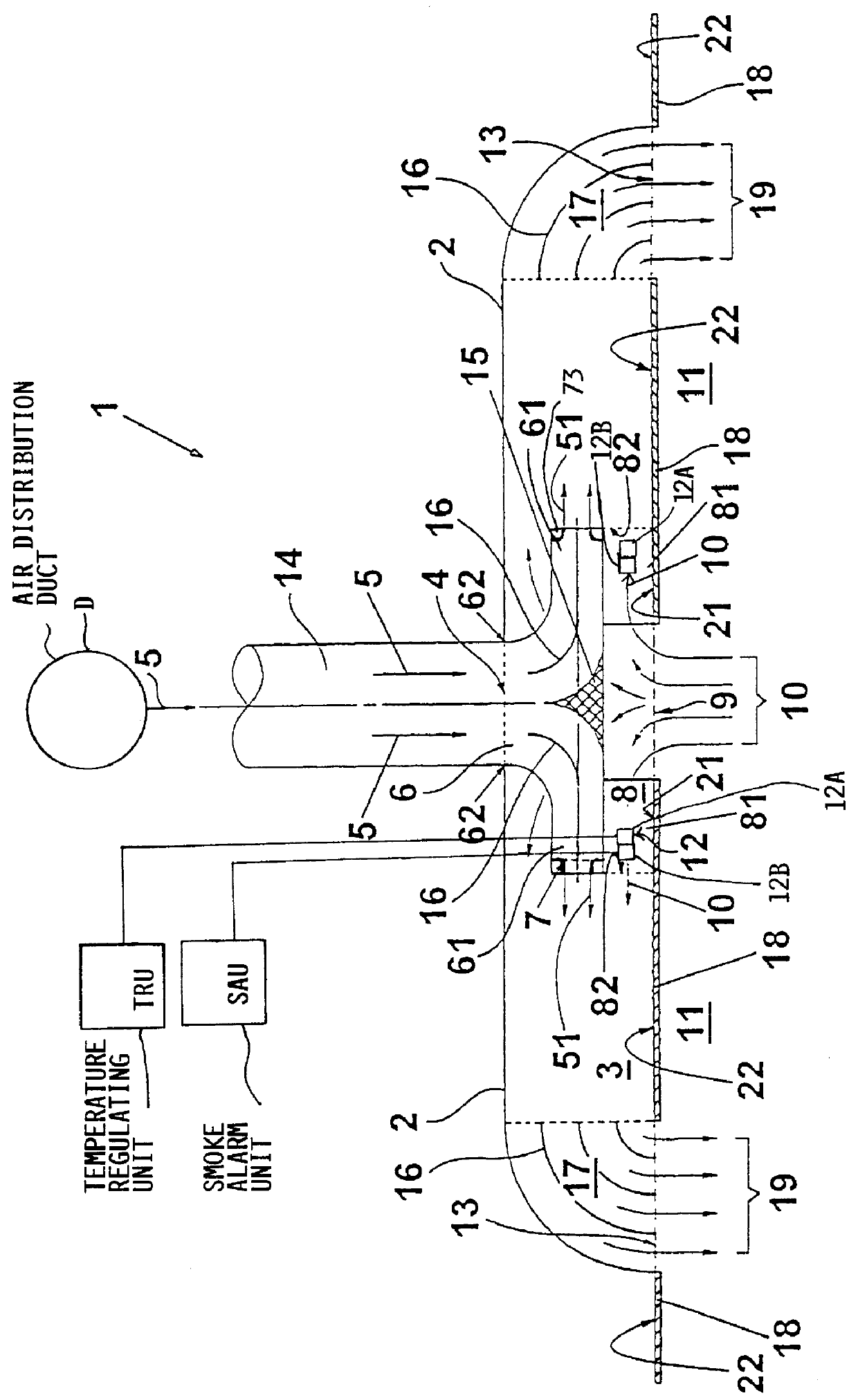
The single FIGURE is a general schematic sectional overview of an injector air outlet 1 according to the invention, taken along a vertical section plane, for example. In this example, the air injector outlet 1 may be installed in the ceiling of an enclosed space 11, such as a passenger cabin or freight compartment, of an aircraft, for carrying out temperature monitoring and / or smoke monitoring of the air within the enclosed space 11 while simultaneously circulating air into the space 11. Alternatively, the injector air outlet 1 may be installed in the side walls, or in any other trim component within the aircraft fuselage.

While it is not apparent in the view of FIG. 1, the injector air outlet 1 may have a uniform circular plan shape, or an elongate rectangular plan shape, or a square plan shape, or some other shape when viewed in a direction from the bottom of FIG. 1. If the injector air outlet has a square or rectangular plan shape, it may have two or four of each of the air branch...


PUM


Abstract

An injector air outlet includes a temperature sensor and a smoke sensor to simultaneously carry out the functions of air recirculation and temperature and smoke monitoring within a closed interior space, such as a passenger cabin or a freight or cargo hold in an aircraft. The injector air outlet includes a housing wall (2) with an injector mixing chamber (3) therein. A primary supply air inlet (4) receives primary supply air (5) from the aircraft's air distribution duct network, and blows the primary supply air through an injection nozzle (7) into the mixing chamber (3) so as to create a reduced or negative pressure in the mixing chamber. Cabin exhaust air (10) is sucked through a secondary air inlet (9) and a secondary air channel (8) into the mixing chamber (3), due to the reduced pressure or suction effect therein. The primary air and secondary air are mixed together and then ejected forcefully back into the cabin or cargo hold. A sensor unit (12) including a temperature sensor (12A) and a smoke sensor (12B) is installed in the secondary air channel (8) so that a flow of exhaust air (10) is continuously positively caused to flow over the sensor unit (12).

Description

The invention relates to an injector air outlet having a temperature and / or smoke sensor incorporated therein, and a method for monitoring the air temperature and / or the presence of smoke in a closed interior space within the fuselage of an aircraft. The invention particularly applies to such a device and method utilized in the air-conditioning of aircraft freight or cargo hold spaces, within which typical non-hazardous and / or hazardous freight is being stored or transported.BACKGROUND INFORMATIONThe air-conditioning or climate control, i.e. the ventilation with simultaneous heating or cooling, of aircraft freight compartments is conventionally achieved by blowing temperature regulated supply air into the freight compartment at several distributed locations through respective air outlets. After traversing through the cargo or freight compartment, this air exits the freight compartment through respective exhaust openings. A particular air flow pattern or profile through the space is ...

Claims


Application Information

Patent Timeline
IPC IPC(8): B64D13/00B64C13/00B64D13/06
CPCB64D13/00B64D2013/0651B64D2013/0688Y02T50/56Y02T50/50
Inventor SCHERER, THOMASBUCHHOLZ, UWE
Owner DAIMLER CHRYSLER AEROSPACE AIRBUS
Features
  • Generate Ideas
  • Intellectual Property
  • Life Sciences
  • Materials
  • Tech Scout
  • Unparalleled Data Quality
  • Higher Quality Content
  • 60% Fewer Hallucinations
Learn More