Method of electronic control

a technology of electronic control and control method, applied in the direction of pulse position modulation, pulse technique, digital transmission, etc., can solve the problems of literally kilometres of wires, inability to achieve successful communication along the electric fence line, and incorrect operation of the electric fence system

Inactive Publication Date: 2000-02-29
GALLAGHER ELECTRONICS LTD CO
View PDF15 Cites 7 Cited by
  • Summary
  • Abstract
  • Description
  • Claims
  • Application Information

AI Technical Summary

Benefits of technology

It should now be appreciated that the present invention enables communication signals to be received more clearly on systems in a variety of situations including fence and security systems.

Problems solved by technology

Electric fence systems, whether powered by electric fence energisers for stock control or forming part of security systems have a number of unique features and associated problems.
Unfortunately, there are a number of problems associated with electric fence energisers which makes communications along the electric fence line difficult to achieve successfully.
One major problem associated with electric fence systems is that they comprise of literally kilometres of wire.
This noise can include radio waves, pulses from electric fence energisers on neighbouring farms, static electricity build-up from the atmosphere, magnetic fields from nearby mains transformers, radio frequency interference from vehicles and other sources.
All this electrical noise can mean that communication signals sent along the fence line are either not detected by the appropriate receivers (as the communications signal is masked by the noise), or that the receivers interpret incorrectly the noise as being a communication signal.
Either way, the presence of electrical noise along the fence line can lead to incorrect operation of the electric fence system.
Unfortunately some of the noise present on an electric fence line is high frequency noise.
This increases the possibility of signals being picked out from the noise which correspond to the time difference expected in a communications signal under a pulse position modulated system.
A further problem associated with electric fence systems is that the amount of noise on an electric fence line is not constant and varies from electric fence system to electric fence system and can also vary for a single electric fence system over a period of time.
Other factors contributing to the varying electrical noise include the possible presence of electrical noise sources such as radio stations, transmission wires, neighbouring farms, heavy electrical machinery such as pumps and the like.
Because of this varying electrical noise and the associated unpredictability, it is very difficult to design a communications system for an electric fence line that can, no matter what the conditions, guarantee to filter out the appropriate amount of electrical noise while still allowing a sufficiently strong communications signal to be received by receivers in the electric fence system.

Method used


Image

  • Method of electronic control
  • Method of electronic control
  • Method of electronic control

Examples


Embodiment Construction

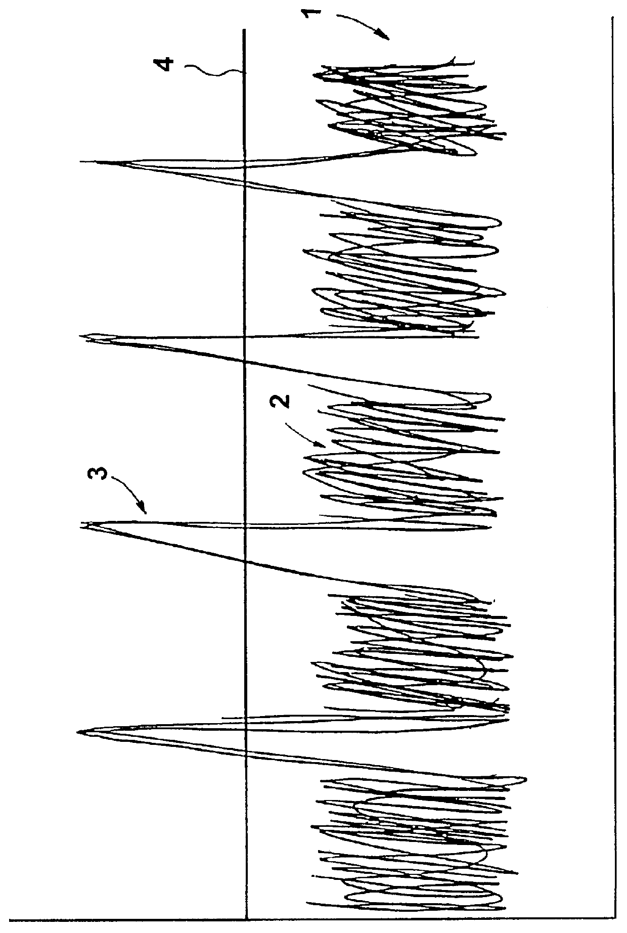
With respect to FIG. 1, there is illustrated a voltage versus time graph of a possible signal on an electric fence line.

The signal generally indicated by arrow 1 is comprised of two components, namely high frequency noise 2 and communication signal pulses 3.

The communication signal pulses 3 have a higher voltage than the noise 2. Thus, if a filter having a threshold value 4 is applied, then only the signal pulses 3 will pass through the filter and into the signal receiver.

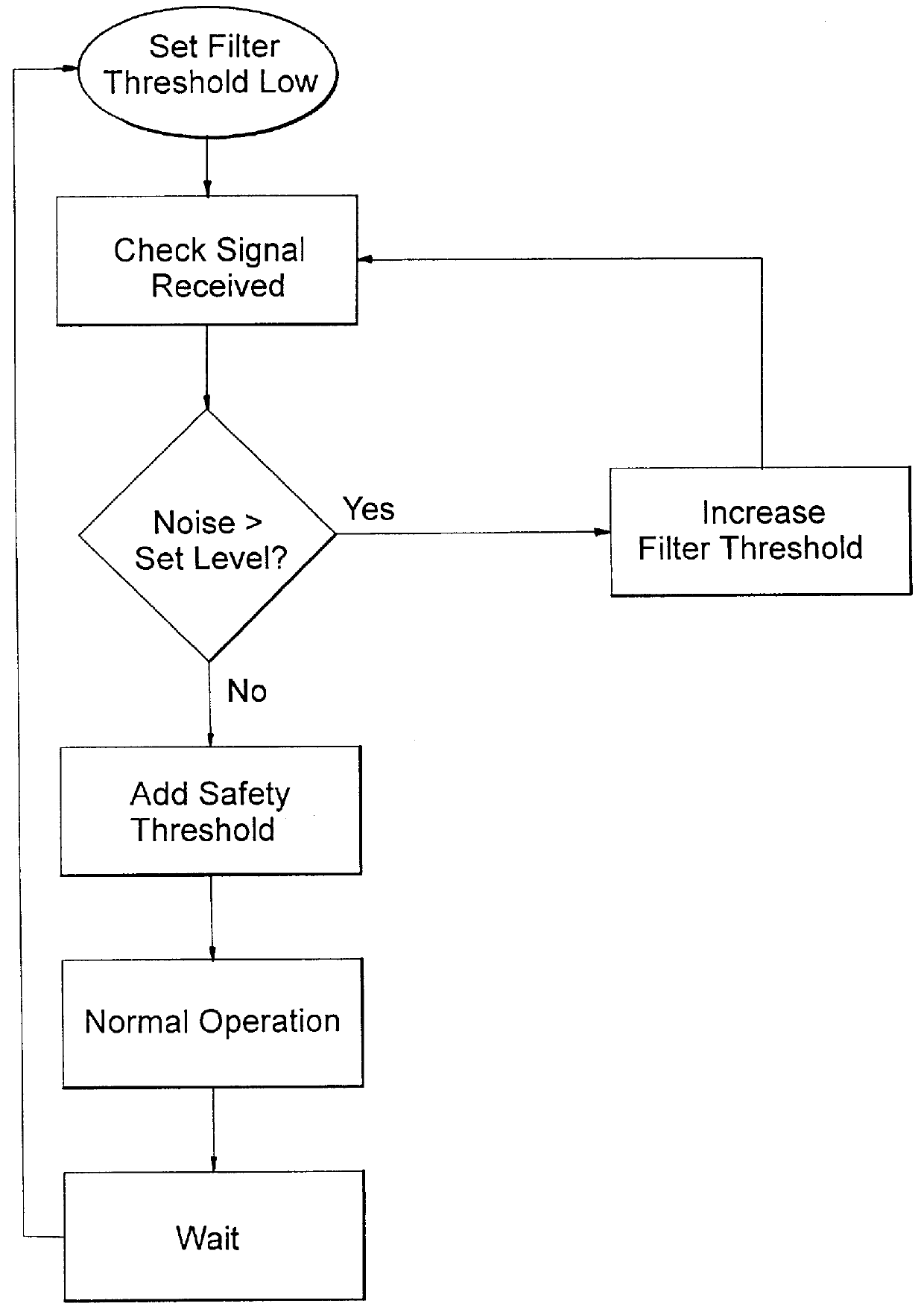
FIG. 2 illustrates a possible algorithm by which one embodiment of the present invention can operate.

Initially the filter threshold is set low. Then the amount of noise passing through the filter is checked. If there is noise above a set level, then the filter threshold is increased and the signal checked until no noise passes through the filter. Once this has been achieved, a safety threshold is added to account for higher than average noise levels occurring. Then, the communication system can operate as normal. A...


PUM


Abstract

PCT No. PCT/NZ95/00123 Sec. 371 Date Jun. 13, 1997 Sec. 102(e) Date Jun. 13, 1997 PCT Filed Nov. 24, 1995 PCT Pub. No. WO96/17440 PCT Pub. Date Jun. 6, 1996A method and device for detecting on an electric fence system a communication signal from a total signal including noise and also electrical interference from electrical energizer pulses supplied to the fence. A signal detector detects, directly or indirectly, the level of noise or electrical interference in the total signal on the system, at least one of a filter associated with the signal detector and the amplitude of the total signal received is adjusted until the threshold of the filter blocks sufficient electric noise so that a sufficient part of the total signal received after filtering is the communication signal, and the adjustment of the filter threshold is not dependent on the communication signal alone. The validity of the communication signal is checked and the electrical energizer pulses are transmitted on the fence system in coordination with reception of the communication signals to reduce the interference.

Description

This invention relates to a method of electronic control.Reference throughout this specification shall be made to use of the present invention with respect to electric fence systems, however it should be appreciated that the principles of the present invention can be applied to other systems as well.Electric fence systems, whether powered by electric fence energisers for stock control or forming part of security systems have a number of unique features and associated problems.Electric fence systems are becoming more and more sophisticated and in recent times there has been a number of developments in which electric fence lines are used to carry communication signals. These signals are generally used for turning electric fence energisers on or off and / or checking the status of various sectors of the electric fence system. Some of these developments are described in New Zealand Patent Application Nos. 245206 and 239506.Unfortunately, there are a number of problems associated with elec...

Claims


Application Information

Patent Timeline
Patent Type & Authority Patents(United States)
IPC IPC(8): H04B1/10H05C3/00
CPCH04B1/10H05C3/00
Inventor WALLEY, JOHN LEONARD
Owner GALLAGHER ELECTRONICS LTD CO
Why Eureka
Try Eureka