Apparatus for controlling the inflation pressure of a mattress in response to deformation of the mattress using impedance measurement

a technology of impedance measurement and mattress, which is applied in the direction of mattresses, coils, seating furniture, etc., can solve the problems of not being able to meet the needs of the applicant, damping the signal delivered to the amplifier by the oscillator, and the prior device suffers from the drawback of non-desirable frequency variation in the operation of the prior devi

Inactive Publication Date: 2000-03-07
HILL ROM INDS
View PDF14 Cites 74 Cited by
  • Summary
  • Abstract
  • Description
  • Claims
  • Application Information

AI Technical Summary

Benefits of technology

A further main object of the present invention is to provide a solution that makes it possible to keep frequency substantially constant in an inductive system for measuring the positioning of an element whose shape frequently varies, thereby improving electromagnetic compatibility.
In a fourth aspect, the present invention further provides a method of treating bedsore or lowering the risk of occuring of bedsore of a patient lying on a mattress, comprising:

Problems solved by technology

That device is not very satisfactory because it requires provision to be made to power both induction coils, i.e. including the moving induction coil which is disposed close to the patient, and that always poses a safety problem.
Displacement modifies the self-induction coefficient of the induction coil, shifting the resonant frequency of the LC circuit away from the tuning frequency of the oscillator, thereby damping the signal delivered to an amplifier by the oscillator.
The applicant's prior device therefore suffers from the drawback that operation thereof is based on a non-desirable frequency variation.
Furthermore, the voltage value obtained is low.
In addition, the frequency variation is difficult to make compatible with electromagnetic safety standards.

Method used


Image

  • Apparatus for controlling the inflation pressure of a mattress in response to deformation of the mattress using impedance measurement
  • Apparatus for controlling the inflation pressure of a mattress in response to deformation of the mattress using impedance measurement
  • Apparatus for controlling the inflation pressure of a mattress in response to deformation of the mattress using impedance measurement

Examples


Embodiment Construction

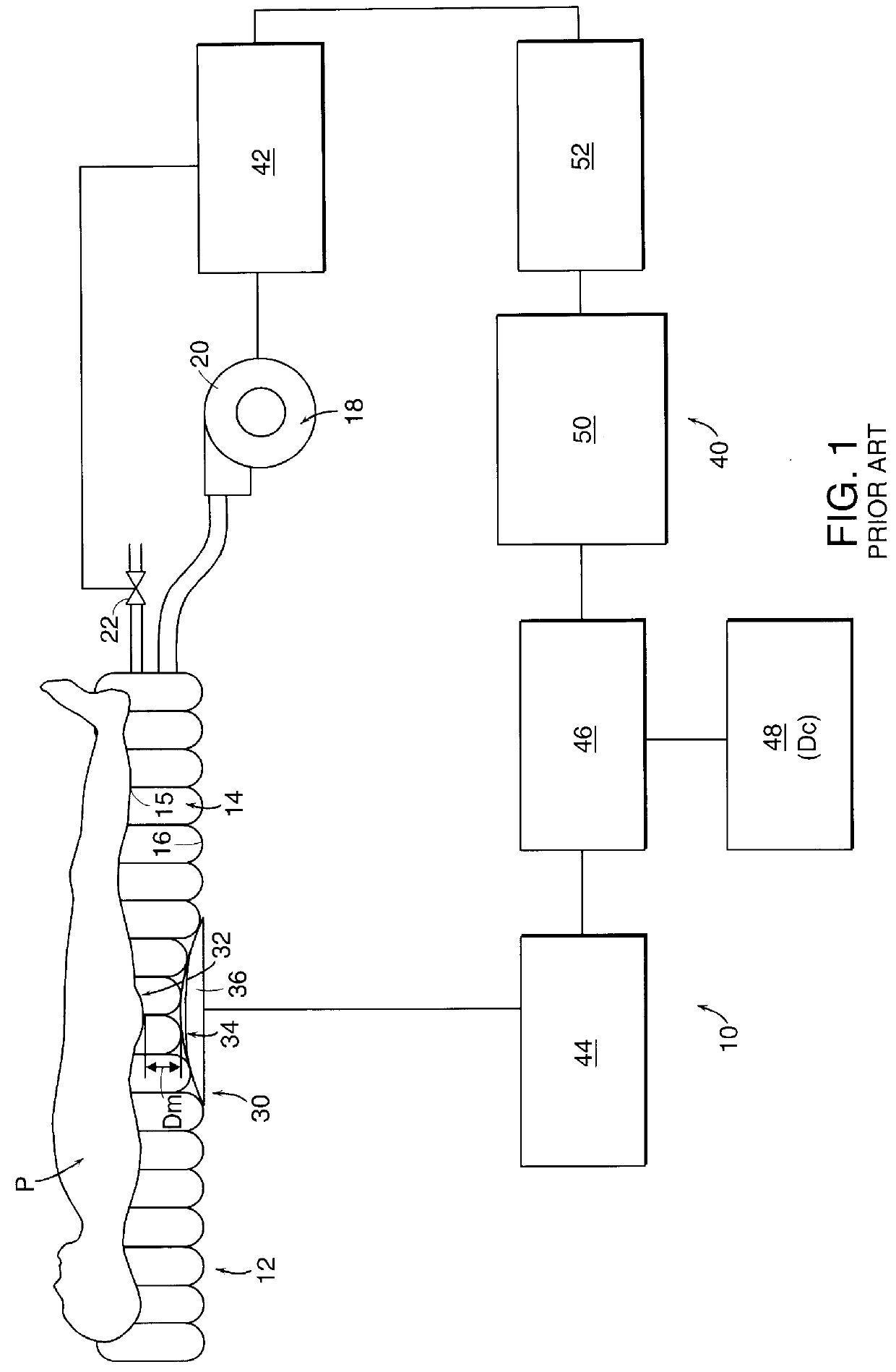
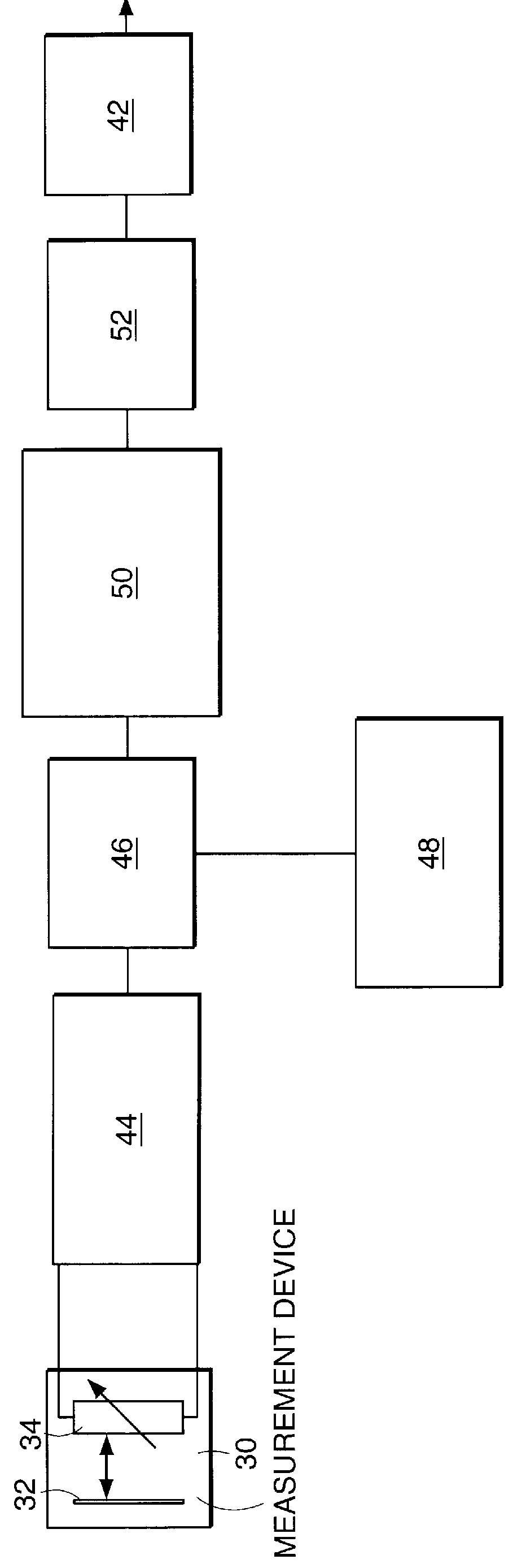
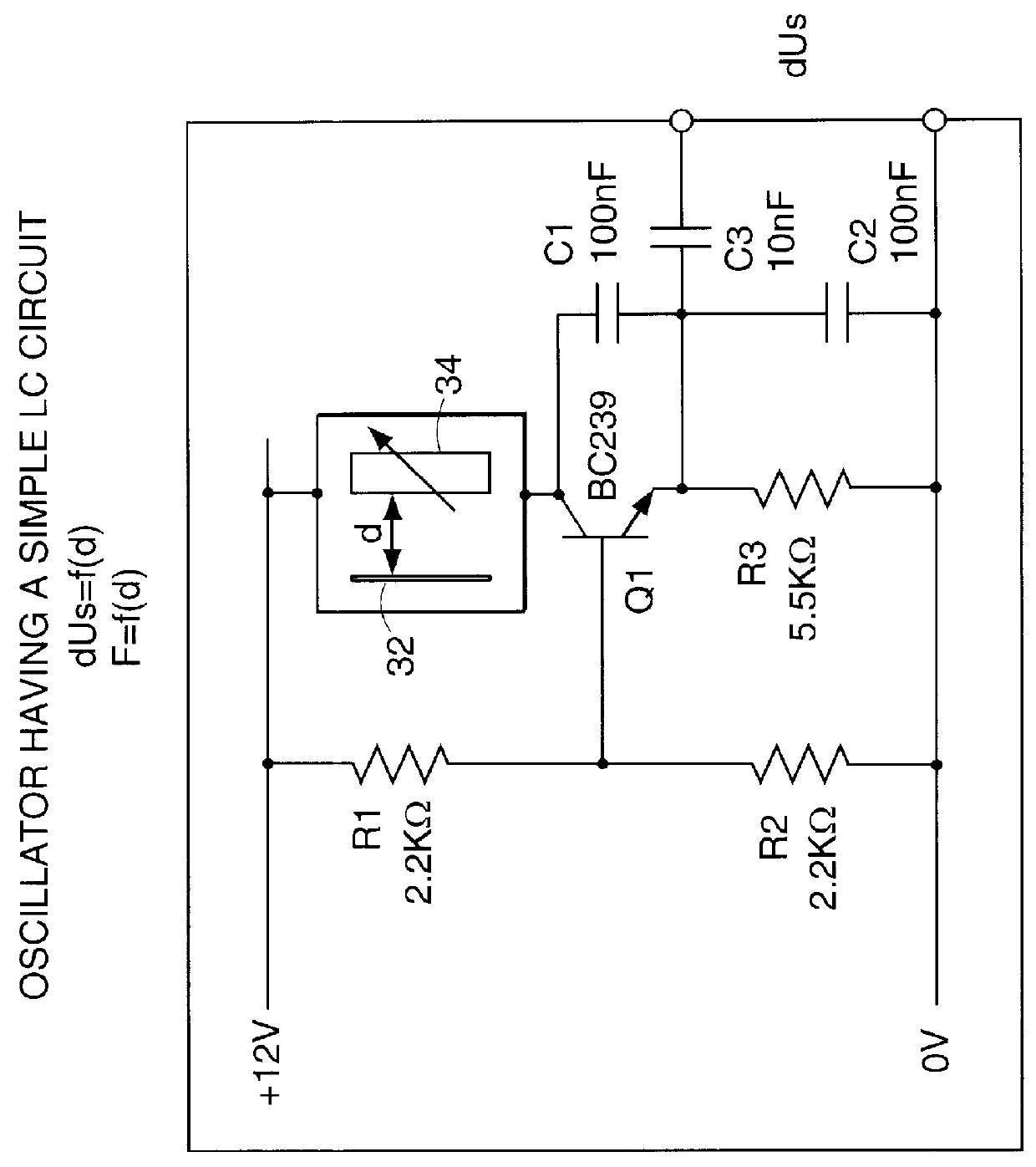
FIG. 1 shows the prior art support apparatus as described in Document FR-A-2 718 347=EP-A-676 158 given the overall reference 10. That support apparatus makes it possible to support an element, in particular the body of a patient P, as shown.

The apparatus 10 includes a deformable support device proper 12, e.g. a mattress, comprising at least one closed or controlled-release chamber 14 that is flexible and inflatable. For example, the chamber may be composed of a multitude of inflatable tubes that communicate with one another, said chamber 14 being inflatable under an adjustable predetermined initial inflation pressure. The chamber 14 has a top face 15 serving to support the element to be supported, preferably patient P, and a bottom face 16 which may, for example, rest on a base (not shown) or on equivalent means. The apparatus further includes servo-control means 18 for servo-controlling the pressure at which the chamber 14 is filled as a function of the distance to which the eleme...


PUM


Abstract

A method and apparatus for supporting a patient on a mattress. The apparatus includes a mattress which has at least one controlled release chamber with a top face and a bottom face. A flexible film of a thin metal foil is linked to the top face, while at least one impedance varying device is linked to the bottom face of the chamber. The impedance varying device is an integral part of a measuring electronic bridge. Changes in the impedance as a result of movement of the top face with respect to the bottom face activates a servo control which increases or decreases the inflation pressure within the chamber to make certain that the distance between the top face and the bottom face of the chamber is maintained at a predetermined distance. The method of this invention includes the steps of providing a mattress having at least one closed or controlled release chamber having a top face and a bottom face, providing a measurement device which includes a flexible film of a thin metal foil linked to the top face of the chamber and cooperating with at least one impedance varying element linked to the bottom face of the chamber, the impedance varying element being integral with a measuring electronic bridge, and measuring spacing between the top face and the bottom face to provide control of the supporting action of the mattress as a function of the patient's morphology and position on the mattress.

Description

The invention essentially relates to a method and a device integrating an induction coil in a measurement electronic bridge.It is known by the Article published in "Journal de l'Equipement Electrique et Electronique" No. 306, November 1970, pages 116-117, equipments which are temperature compensated for sensing movements of moving surfaces like axles.It is disclosed a method of compensating a thermal derivation by using two transducers located in two branches of an electronic bridge, see FIG. 1, and sufficiently close so that they are supposed to be at the same temperature.One of the transducers named as reference, see FIG. 2, is located in front of a gap which is known and fixed.FIG. 3 shows a total thermal compensating bridge with inductive coils.In that document, the two transducers are fixed and are separated by a known fixed distance.It is also known by German Patent Application DE-A-2550427, corresponding to U.S. Pat. No. 4,160,204, a non-contact distance measuring system comp...

Claims


Application Information

Patent Timeline
Patent Type & Authority Patents(United States)
IPC IPC(8): G01B7/02G01B7/14A61G7/05G01B7/00G01B7/28
CPCG01B7/023G01B7/14A61G2203/40
Inventor MONTANT, JEAN-MARCCAMINADE, JEAN-LUC
Owner HILL ROM INDS
Why Eureka
Try Eureka