Joystick control device having cursor correcting function

a control device and cursor technology, applied in the direction of mechanical control devices, manual control with single controlling member, instruments, etc., can solve the problems of inability to obtain the desired circuit character of a conventional joystick control device, the adjustment resistor changes or the resistor breaks, and the additional micro-adjuster is necessary, etc., to achieve the same superior performance, eliminate the effect of ill effects and easy correction

Inactive Publication Date: 2000-03-07
REALTEK SEMICON CORP
View PDF4 Cites 26 Cited by
  • Summary
  • Abstract
  • Description
  • Claims
  • Application Information

AI Technical Summary

Benefits of technology

is to provide a joystick control device having cursor correcting function wherein the conventional adjustable resistor is replaced by a photoelectric element for detecting the movement of the joystick, thereby eliminates the ill effects caused by mechanical attrition of the adjustable resistor. Additionally, the circuit parameter drifts caused by IC manufacturing processes can be easily corrected by the correction function of joystick; therefore, every individual mass-produced IC has the same superior performance.

Problems solved by technology

These conventional joystick control devices are disadvantage in that the resistance of the adjustable resistor changes or the resistor breaks after long time usage, with the result that the cursor does not sit at the central point of the screen as the joystick stays at its central position, and that an additional microadjuster for compensation is necessary.
Besides, the desired circuit characters of a conventional joystick control device may not be obtained because of the parameter drift and variation caused by the manufacturing processes; therefore, the cursor positions on a screen for the mass-produced joystick control devices are not congruous.

Method used


Image

  • Joystick control device having cursor correcting function
  • Joystick control device having cursor correcting function
  • Joystick control device having cursor correcting function

Examples


Embodiment Construction

)

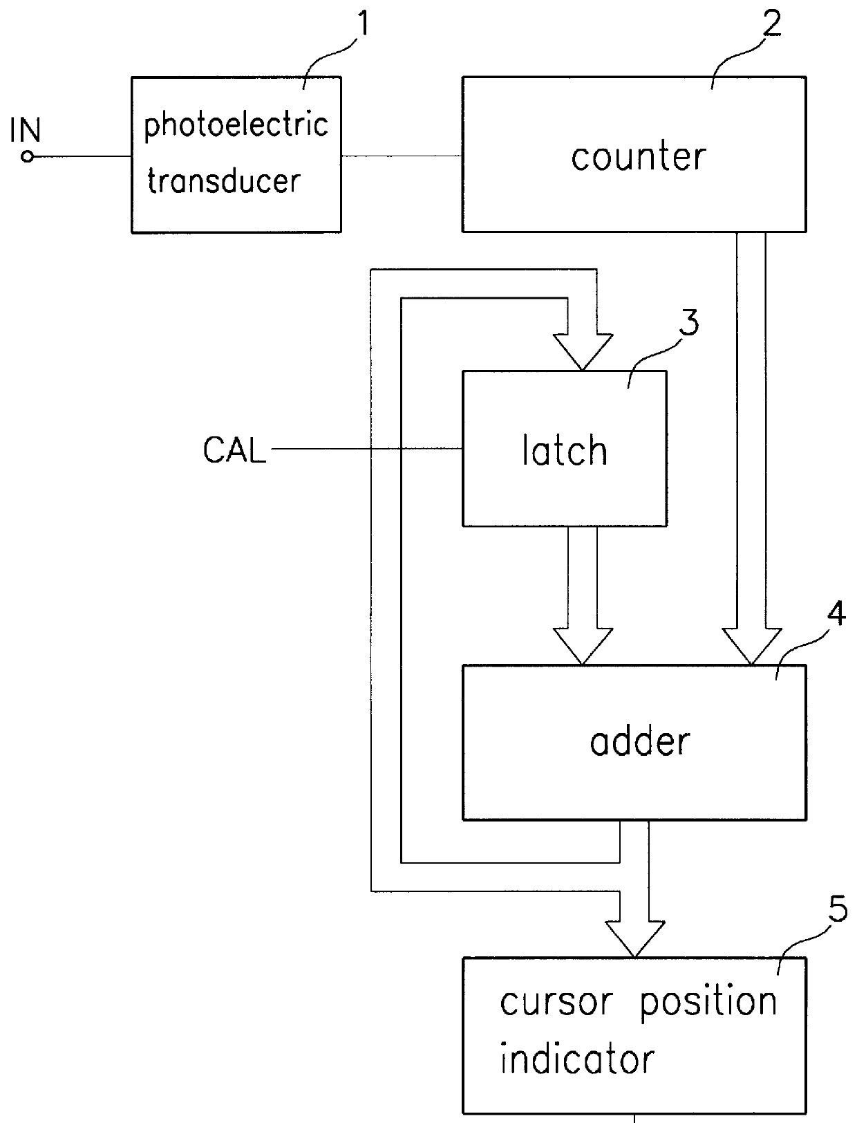
Referring to FIG. 1 the joystick control device having cursor correcting function according to the preferred embodiment of the present invention includes:

a photoelectric transducer 1, connecting to the joystick for transforming the light signal corresponding to the movement of the joystick into a one-byte electrical digital signal;

a counter 2, connecting to the photoelectric transducer 1 for transforming the digital signal (coming from the photoelectric transducer 1) to a bit sequence, wherein the bit sequence represents the movement of the joystick;

a latch 3, having a correction parameter therein and connecting to a feedback signal and a control signal CAL, and selectively inputting the feedback signal to replace the prior correction parameter according to the control signal CAL;

an adder 4, receiving the output parameters from the counter 2 and the latch 3, adding these two parameters, and outputting the result; and

a cursor position indicator 5, receiving the parameter from the ad...


PUM


Abstract

A joystick control device having cursor correcting function, in which the conventional adjustable resistor is replaced by a photoelectric element for detecting the movement of the joystick, thereby eliminates the ill effects caused by mechanical attrition of resistor. Additionally, the parameter drifts caused by IC manufacturing processes are corrected using shift correction of joystick; therefore, every individual mass-produced IC shows similar good behavior.

Description

1. Field of the InventionThe present invention relates to a joystick control device having cursor correcting function.2. Description of the Related ArtFor a conventional joystick control device, movement of the joystick is typically detected by the adjustable resister of its input terminal and, after internal processing, the position of cursor on a screen is determined according to the outputted resistance. These conventional joystick control devices are disadvantage in that the resistance of the adjustable resistor changes or the resistor breaks after long time usage, with the result that the cursor does not sit at the central point of the screen as the joystick stays at its central position, and that an additional microadjuster for compensation is necessary.Besides, the desired circuit characters of a conventional joystick control device may not be obtained because of the parameter drift and variation caused by the manufacturing processes; therefore, the cursor positions on a scre...

Claims


Application Information

Patent Timeline
Patent Type & Authority Patents(United States)
IPC IPC(8): G06F3/033G05G9/00G05G9/047G06F3/038
CPCG05G9/047G06F3/0383G05G2009/04759
Inventor CHIANG, TING-CHICHENG, FU-YUANCHEN, HUAI-YI
Owner REALTEK SEMICON CORP
Why Eureka
Try Eureka