Optical network and arrangement and method in such network

a technology applied in the field of optical network and arrangement and method in such network, can solve the problems of affecting signal quality, unable to adapt known solutions to layered networks,

Inactive Publication Date: 2000-03-07
TELEFON AB LM ERICSSON (PUBL)
View PDF9 Cites 36 Cited by
  • Summary
  • Abstract
  • Description
  • Claims
  • Application Information

AI Technical Summary

Problems solved by technology

A disadvantage with this known solution is that it is only intended for communication between two structurally similar ring networks which communicate only with each other.
If the known solution is applied to an optical network, the ring structure causes optical noise to circulate in the ring network, which impairs signal quality.
Furthermore the known solution cannot be adapted to layered networks having a plurality of different levels and a plurality of loops in each level.

Method used


Image

  • Optical network and arrangement and method in such network
  • Optical network and arrangement and method in such network
  • Optical network and arrangement and method in such network

Examples


embodiment

PREFERRED EMBODIMENT

In the following the invention will be explained with reference to the Figures and in particular to FIGS. 2, 4 and 5 which show preferred embodiments of a lower-order loop disposed in an optical network.

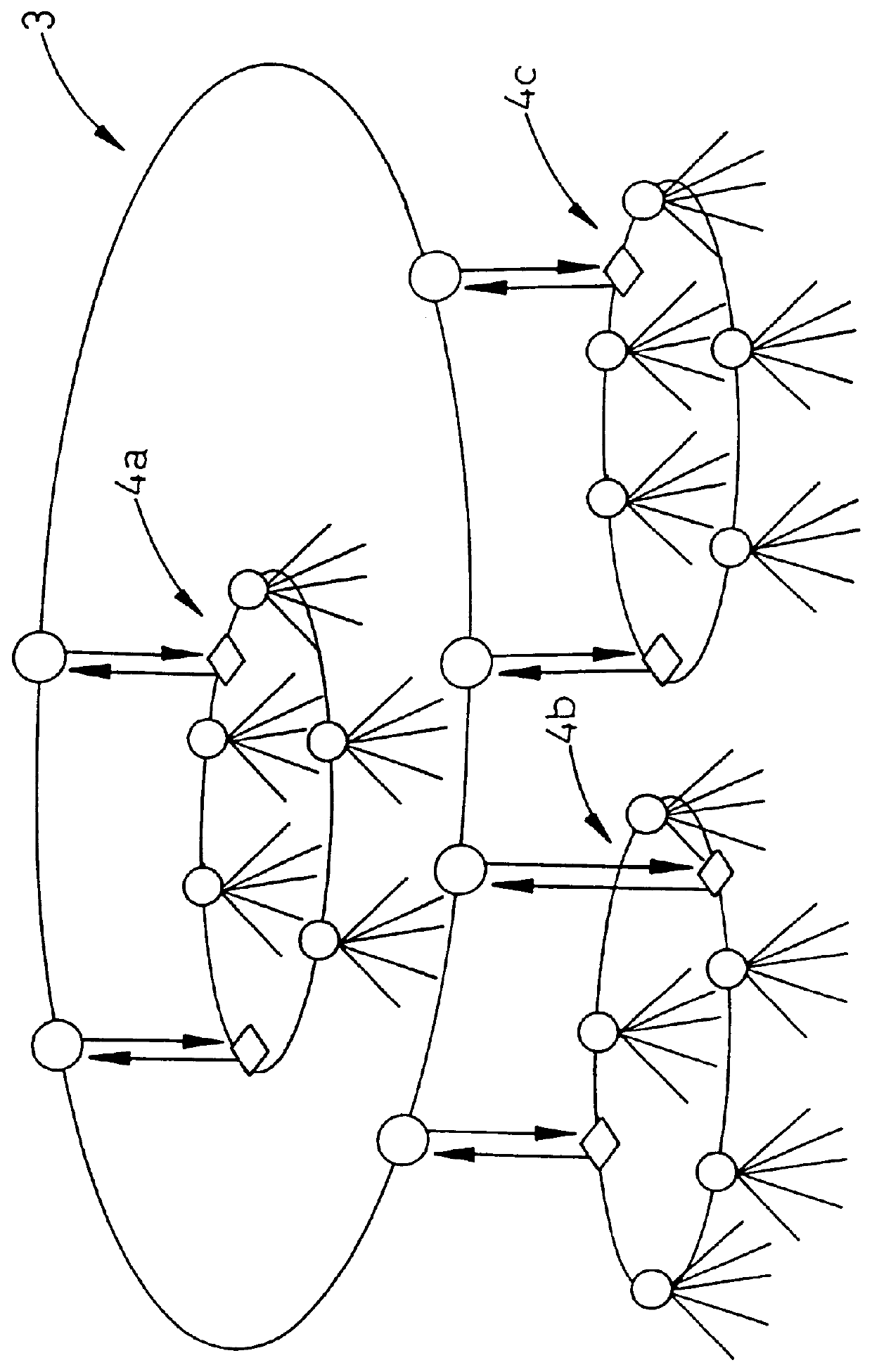
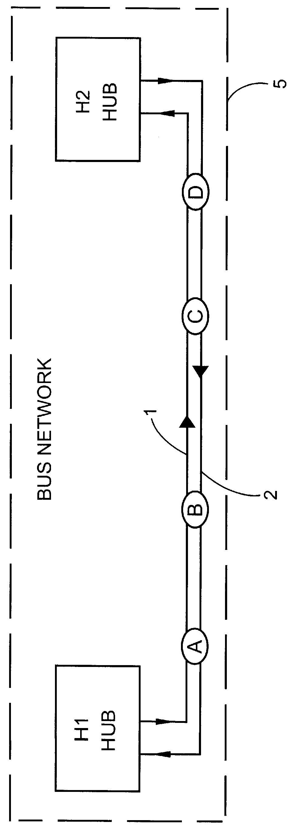
FIG. 1 shows schematically a known construction for an optical network which is constructed as a layered network. In the example shown in the Figure, the network comprises three lower-order loops 4a-4c which communicate via a higher-order loop 3. Each lower-order loop comprises one or a plurality of nodes, shown as circles in the Figures. The optical nodes are connected to one another via two oppositely-directed optical fibres and communicate with one another via two hubs which are disposed in the loop and which are shown as rhombi in the Figures. Hubs are also used for communication between nodes in different lower-order loops, the higher-order loop being used for transmitting information between two hubs in inter-communicating loops. The so called hubs are arran...


PUM


Abstract

PCT No. PCT / SE96 / 00374 Sec. 371 Date Dec. 29, 1997 Sec. 102(e) Date Dec. 29, 1997 PCT Filed Mar. 26, 1996 PCT Pub. No. WO96 / 31964 PCT Pub. Date Oct. 10, 1996An optical network which is arranged to ensure communication between nodes in a lower-order loop and a higher-order loop when there is an interruption in the lower-order loop or in the event of hub failure. Each lower-order loop consists of a bus network with hubs and one or a plurality of nodes. Two optical fibers connect the nodes in each bus network and are used for communication in opposite directions between the nodes. Each bus network comprises precisely two hubs of which the first closes the bus network end at the first end thereof and the second closes the bus network at the other end. The hubs connect the bus networks in a lower-order loop and join this loop to a higher-order loop. Each node in the bus network is arranged to communicate with each hub. Channel allocation can be carried out so that channels received in one node are re-used for transmission on the same fiber from the same node.

Description

The present invention concerns an optical network which is arranged to ensure communication between nodes in a lower-order loop and a higher-order loop when there is an interruption in the lower-order loop.The invention also concerns a process for allocating channels in the aforementioned optical network.PRIOR ARTWithin the field of telecommunications there is frequently a need for very high transmission capacity. Data can be transmitted very rapidly by means of optical transmission via modulated light signals.Large optical networks are frequently constructed as layered or hierarchical networks comprising lower-order or local loops and higher-order or central loops. The lower-order loops are formed by nodes to which a plurality of network subscribers are connected. The nodes are preferably connected to one another via two optical fibres in which messages are sent in opposite directions. Communication between nodes in different lower-order loops is performed in that the messages from...

Claims


Application Information

Patent Timeline
Patent Type & Authority Patents(United States)
IPC IPC(8): H04J14/02H04B10/213H04L12/437H04L12/46H04L12/44H04B10/27H04B10/275H04B10/278
CPCH04B10/271H04B10/275H04B10/278H04J14/0227H04J14/028H04J14/0283H04L12/437H04L12/4637H04L12/44H04J14/02H04L12/42
Inventor OBERG, MAGNUS
Owner TELEFON AB LM ERICSSON (PUBL)
Why Eureka
Try Eureka