

Variable focus lens by small changes of the equatorial lens diameter
- Summary
- Abstract
- Description
- Claims
- Application Information
AI Technical Summary
Benefits of technology
Problems solved by technology
Method used
Image

Examples
an embodiment 500
of the variable focus lens of the invention is illustrated in FIGS. 10 and 11. This embodiment of the invention uses a metal ring 506 embedded in the rim 504 of the lens 502 or bonded thereto. When the metal ring 506 is heated it expands, thereby increasing the equatorial diameter of the lens 502 and increasing its optical power. The metal ring 506 could be heated by an adjacent heating coil of the type illustrated in FIGS. 5 and 6. The metal ring could be heated by other means as well. For example, the ring could be made of a ferromagnetic material and the lens could be surrounded with a coil carrying an alternating current which would heat the ring by electromagnetic induction. The ring could also be heated by radiant energy.
Another embodiment of the invention wherein the radial tension that increases the radial diameter is applied by tensioning screws that stretch the periphery of the elastically deformable lens over an anvil is illustrated in FIGS. 7 and 8. In this apparatus 300...
example
This example illustrates the variation in optical power of an elastically deformable lens that can be achieved by making small changes in the equatorial diameter of the lens.
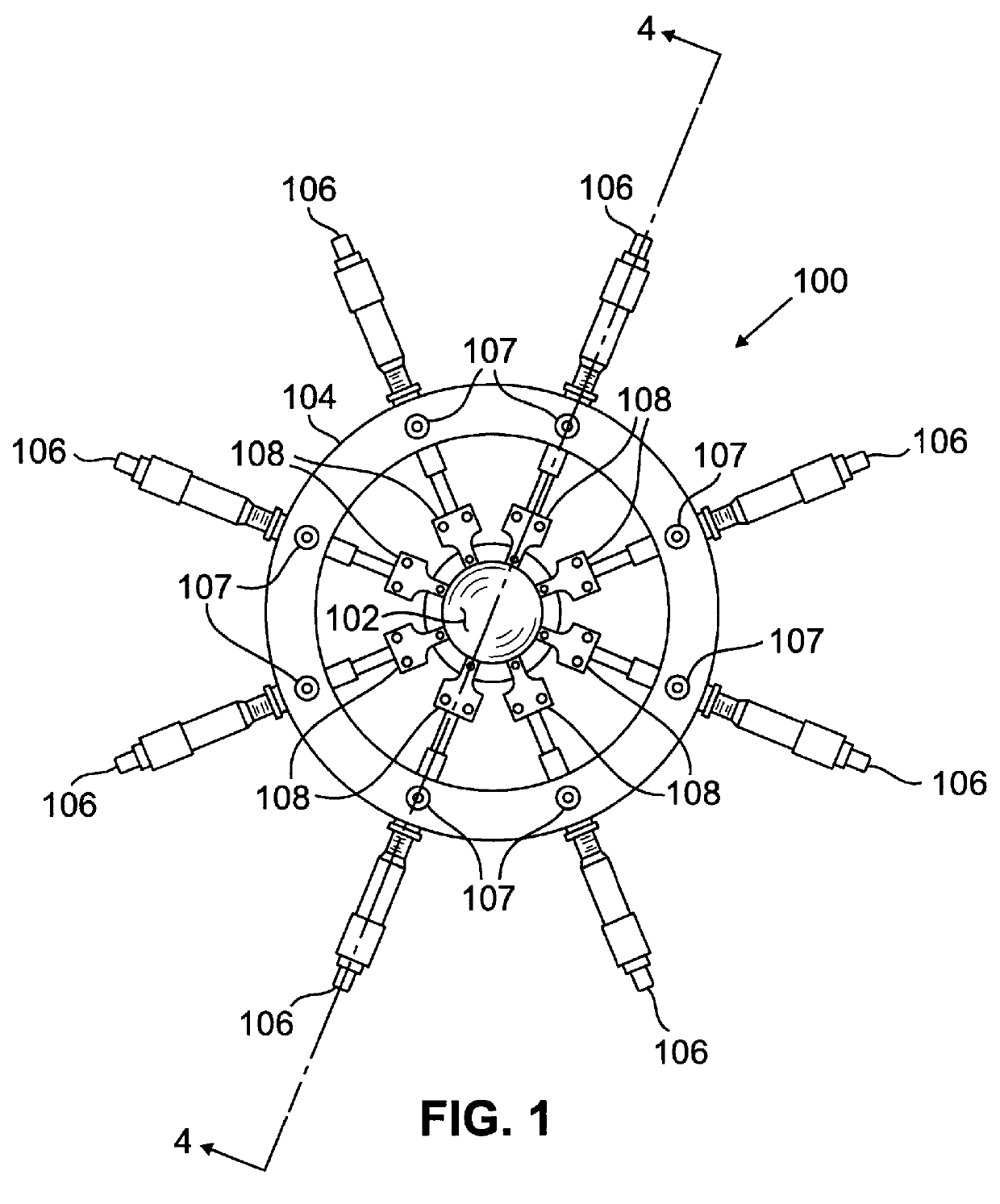
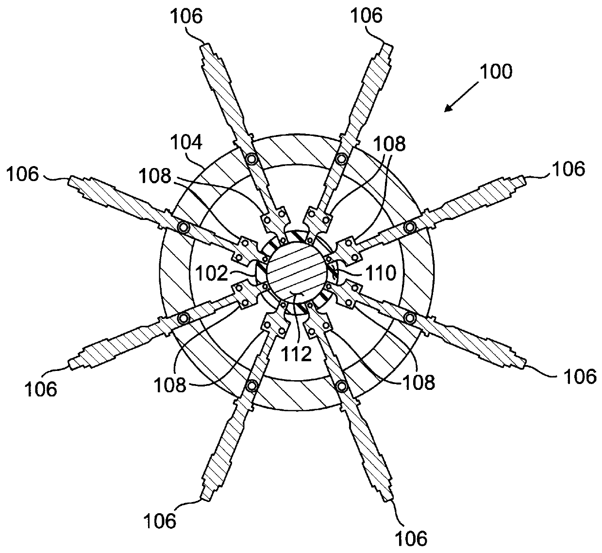
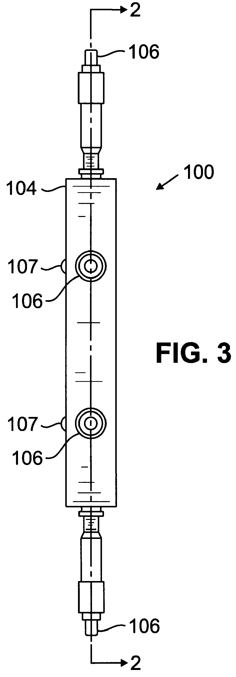
An experimental apparatus of the type illustrated in FIGS. 1-4 was constructed and used to measure the change in optical power achievable by making small changes in the equatorial diameter of an elastically deformable lens tested in the apparatus.
Three transparent plastic, polyvinyl chloride balloons were constructed of polyvinyl chloride having a Young's modulus of 2.4-4.1 GPa and an index of refraction of 1.50-1.55. The balloons were made by heat sealing two webs of the polyvinyl chloride material, having a thickness of about 0.5 mm, together leaving a lip of about 3 mm width extending radially outward from the equator of the lens all around the balloon. The balloons were then filled with water and sealed. The balloons were numbered 1, 2 and 3, and had dimensions as set forth in Table 1 below. The thickness wa...
PUM
 Abstract
Description
Claims
Application Information