Fuel injection valve

a technology of fuel injection valve and fuel injection chamber, which is applied in the direction of combustion types, machines/engines, lighting and heating apparatus, etc., can solve the problem of relative high production cos

Inactive Publication Date: 2000-03-21
ROBERT BOSCH GMBH
View PDF14 Cites 88 Cited by
  • Summary
  • Abstract
  • Description
  • Claims
  • Application Information

AI Technical Summary

Problems solved by technology

A fuel injection valve is already known (German Patent Application DE 42 21 185 A1) in which the valve seat body is produced by

Method used


Image

  • Fuel injection valve
  • Fuel injection valve
  • Fuel injection valve

Examples


Embodiment Construction

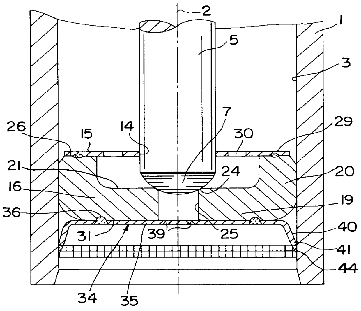
In FIG. 1, an example of an otherwise already known fuel injection valve for fuel injection systems of mixture-compressing internal combustion engines with externally supplied ignition is shown in fragmentary form; it is embodied according to the invention as the first exemplary embodiment. The fuel injection valve has a tubular valve housing 1, in which a longitudinal opening 3 is formed, concentric with a longitudinal valve axis 2. A valve needle 5, for instance of rodlike shape, is disposed in the longitudinal opening 3, and its downstream end is embodied as a spherical portion that serves as a valve closing body 7.

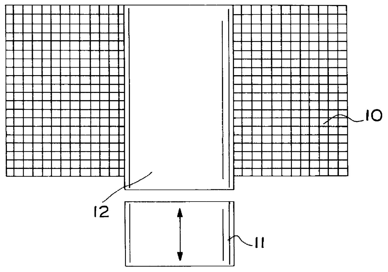
The fuel injection valve is actuated in a known manner, for instance electromagnetically. For axially moving the valve needle 5 and thus opening the fuel injection valve counter to the spring force of a restoring spring, not shown, or closing the fuel injection valve, and electromagnetic circuit shown in suggested fashion in the drawing is used, having a magnet coil 10...


PUM


Abstract

PCT No. PCT/DE97/00533 Sec. 371 Date Apr. 1, 1998 Sec. 102(e) Date Apr. 1, 1998 PCT Filed Mar. 15, 1997 PCT Pub. No. WO98/05859 PCT Pub. Date Feb. 12, 1998A fuel injection valve for internal combustion engines is already known in which the valve seat body is produced by multiple complicated work processes. In the novel valve, a valve seat body of simple design that can be made economically is used. The valve seat body (16) is made from sheet metal by stamping and deep drawing and has a cup shape with a bottom (19) of the seat body and an annular edge (20) of the seat body. A valve seat (24) is formed in the bottom (19) of the seat body. An injection port disk (34) is joined by welding to the valve seat body (16). The fuel injection valve is especially suitable for fuel injection systems of mixture-compressing internal combustion engines with externally supplied ignition (FIG. 1).

Description

PRIOR ARTThe invention is based on a fuel injection valve as generically defined by the preamble to claim 1. A fuel injection valve is already known (German Patent Application DE 42 21 185 A1) in which the valve seat body is produced by complicated work processes, which along with the relatively high material costs also leads to relatively high production costs.ADVANTAGES OF THE INVENTIONThe fuel injection valve according to the invention having the definitive characteristics of claim 1 has the advantage over the prior art that the valve seat body can be produced in a simple, material-saving way, and particularly in large-scale mass production, this leads to a significant cost savings. Designing the valve seat body of sheet metal not only makes for easy machinability and low weight of the valve seat body but also reduces the amount of material required.By means of the provisions recited in the dependent claims, advantageous refinements of and improvements to the fuel injection valve...

Claims


Application Information

Patent Timeline
IPC IPC(8): F02M61/00F02M61/18F02M51/06F02M61/12
CPCF02M51/0653F02M51/0671F02M61/1853F02M51/06F02M61/18
Inventor REITER, FERDINAND
Owner ROBERT BOSCH GMBH
Why Eureka
Try Eureka