T-shirt bag rack with cantilevered bag support arms and method

a bag support and cantilever technology, applied in the direction of machine supports, sport apparatus, wing accessories, etc., can solve the problems of waste of materials, no longer supporting the sides, and plastic bag racks still do little more to improve the actual packing of bags, etc., and achieve the effect of easy removal

Inactive Publication Date: 2000-03-28
HANDLE HELPER
View PDF20 Cites 59 Cited by
  • Summary
  • Abstract
  • Description
  • Claims
  • Application Information

AI Technical Summary

Benefits of technology

Briefly described, the bag rack of the present invention includes a rear extension secured to the bag support arms and extending behind a back wall of the bag rack. The back wall includes a channel for coupling to the rear extension so that a downward force on the forwardly extending bag support arms biases the rear extension into the channel and ensures th

Problems solved by technology

For all their advantages and speed in opening bags, however, plastic bag racks still do little more to improve actual packing of the bag than to suspend the bag in an open position.
When they are removed and placed on the counter or in a shopping cart, the sides are no longer supported and, as a result, they slump down as the groceries shift and lean against the thin sides of the bag that offer no support.
Lower item counts per bag lead to higher bagging costs and also waste material.
Such a proper packing procedure requires considerable care because the thin, flexible sides of the bag provide no support for the initial items around the bag's perimeter.
Packing with one hand not only slows the bagging process, repetitive leaning and reaching can introduce ergonomic hazards as well.
Again, plastic bag racks have made very little real progress in addressing the difficulty inherent in packing thin, flexible, difficult to control bags.
Such careful packing of the bags is seldom accomplished.
The situation is exacerbated by the youth and high rates of turnover among store employees hired to pack bags.
The demands placed on baggers to get customers through the checkout line result in poorly packed, and therefore under-filled bags.
Retailers complain about the under filling of plastic bags and the associated costs

Method used


Image

  • T-shirt bag rack with cantilevered bag support arms and method
  • T-shirt bag rack with cantilevered bag support arms and method
  • T-shirt bag rack with cantilevered bag support arms and method

Examples


first embodiment

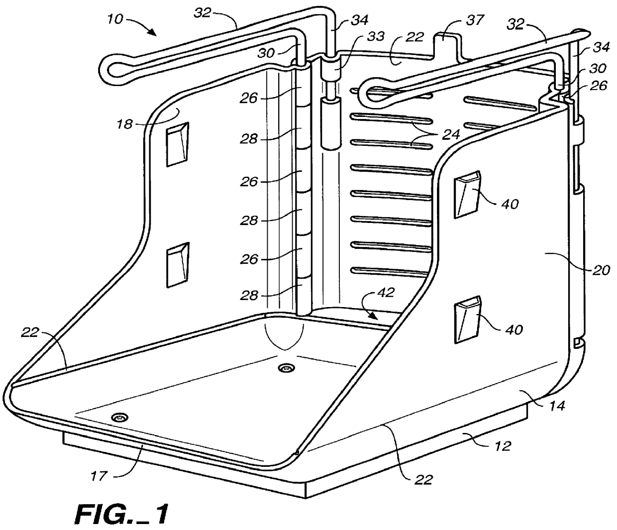
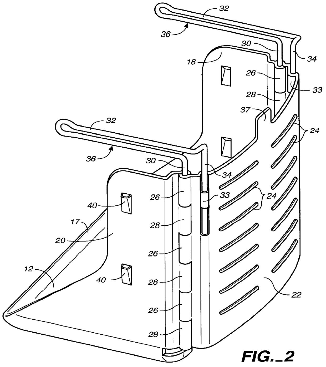
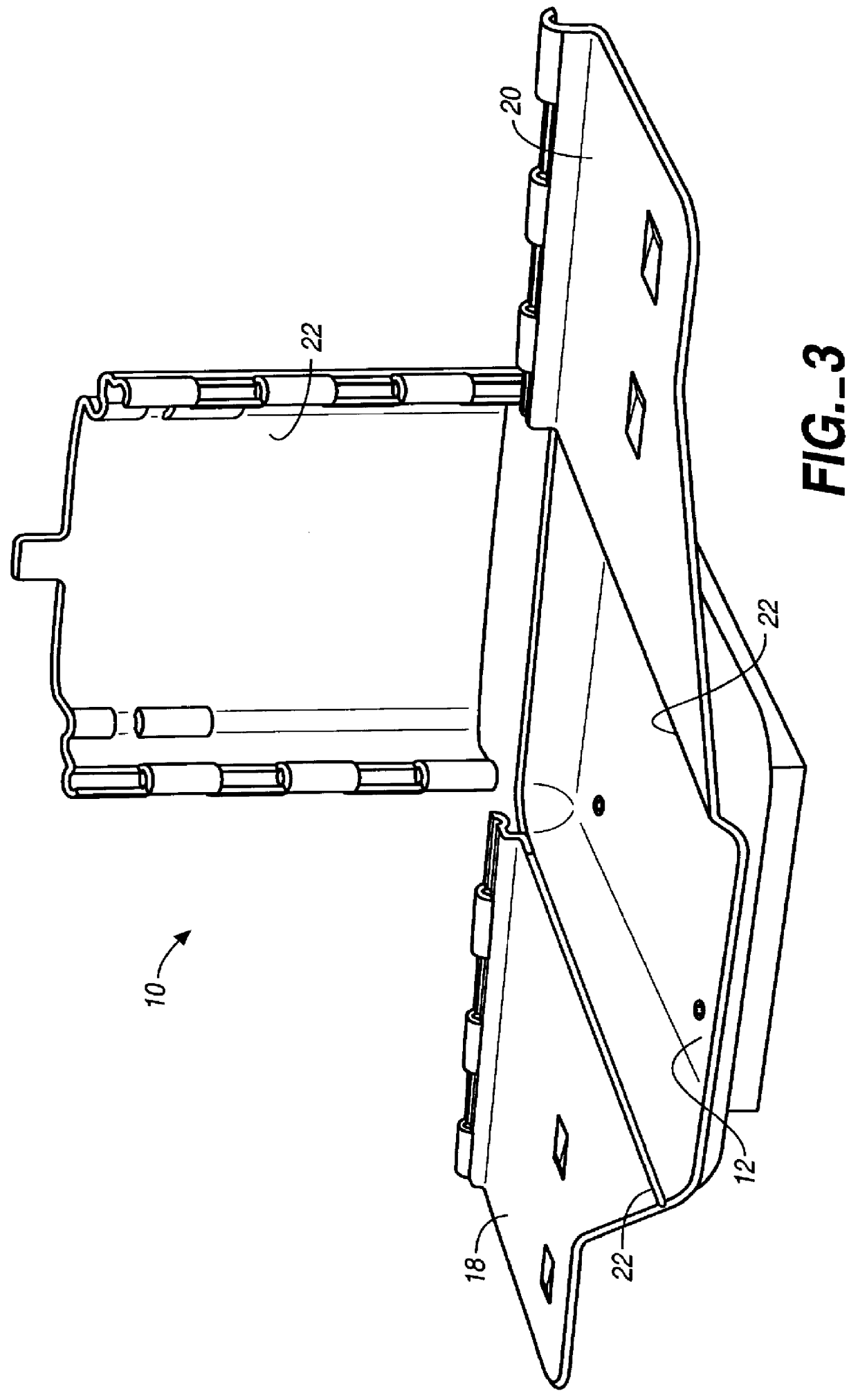
Referring to FIG. 1, the bag rack 10 of the present invention includes a rectangular base 12 having upwardly turned side edges 14, an upwardly turned back edge 16, and an upwardly turned front edge 17 that is formed lower than side edges 14.

Bag rack 10 includes a pair of left and right side walls 18, 20 and a detachable back wall 22. Preferably, side walls 18, 20 are formed monolithically with base 12, with thin wall hinges 22 formed at the upper edges of side edges 14, which allow side walls 18, 20 to fold from an upward position, as shown in FIG. 1, to a substantially flat orientation for stacking, as shown in FIG. 5.

Forming side walls 18, 20 monolithically with base 12 in a substantially flat orientation and separately forming the substantially flat back wall 22, rather than forming these elements together in a cubic configuration, also simplifies the manufacturing process and obviates the need for costly injection molding slides.

Side walls 18, 20 are formed so that they are not ...

second embodiment

FIGS. 8-12 illustrate the bag rack dispenser of the present invention. In FIG. 8, bag rack and dispenser 110 is essentially a three-piece assembly that includes a base 112 formed monolithically with a pair a side walls 114, 116, a back wall 118 formed separate from base 112 and side walls 114, 116, and a wire rod bag support arm assembly 120.

Base 112 and side walls 114, 116 are made by an injection molded plastic process as a single component piece with thin wall hinges 122 that allow side walls 114, 116 to pivot outwardly and down into a flat configuration so that the base and side walls can be stacked in an efficient arrangement. This feature is common to the first bag rack embodiment shown in FIGS. 1-5.

Base 112 includes a set of four countersunk screw recesses 124, which allow for mounting of bag rack 110 upright on a horizontal surface, such as a check-out counter top, by screws (not shown). Screw cover caps 126 fill in the countersunk recesses 124 and thereby cover the screw he...


PUM


Abstract

A bag rack (10, 110, 210) including a base (12, 112), side walls (18, 20, 114, 116), a back wall (22, 118) and a pair of L-shaped bag support arms (32, 160, 162). Side walls (18, 20, 114, 116) are releasably joined and secured to back wall (22, 118) by the upright legs (30, 146) of bag support arms (32, 160, 162) by means of a series of interlocking, aligned slots (26, 28, 142, 144). A rear slot (42, 172) is provided between back wall (22, 118) and base (12, 112) to allow the bottom edges of a multiplicity of bags carried by a hook (37, 156) to extend back of base (12, 112). An embodiment of the back rack (110) is shown in which the bag supporting arms (160, 162) are coupled together by a transversely extending rear extension (164), which cooperatively engages a structure, preferably pairs of channels (168, 170), on the back wall (118) of the bag rack (110) to secure the bag supporting arms (160, 162) in a desired vertical height and to transfer cantilever loading of the bag supporting arms (160, 162) to the back wall (118).

Description

This invention relates to bag racks for dispensing and packing of plastic bags, particularly of the T-shirt type and, more particularly, to an improved vertically adjustable bag support arm design and a method for loading items into a T-shirt bag using a bag rack.Plastic T-shirt bags have largely displaced paper bags over the last twelve years in grocery and other major retail markets. One of the major reasons for the market success of plastic bags, aside from their inherent cost advantage, has been the development of racks to manage the thin, flexible and difficult to control bags. Unlike a paper bag that can stand up on its own while being loaded with groceries, plastic bags initially required a packer to hold the bag up in an open position with one hand and load the groceries with the other hand.The primary function of early plastic bag racks was to hold the bags suspended over a base in an open position, freeing the packer to use both hands to load the groceries. Following these...

Claims


Application Information

Patent Timeline
IPC IPC(8): B65B67/00B65B67/12
CPCB65B67/1227E05Y2900/402
Inventor KERR, JONATHAN F.DIETERICH, JR., PETER D.FISCHER, ROY K.
Owner HANDLE HELPER
Why Eureka
Try Eureka