Read error recovery utilizing ECC and read channel quality indicators

a technology of error recovery and read channel, applied in the direction of digital signal error detection/correction, instruments, coding, etc., can solve the problems of affecting the accuracy of the error recovery process

Inactive Publication Date: 2000-03-28
SEAGATE TECH LLC
View PDF24 Cites 82 Cited by
  • Summary
  • Abstract
  • Description
  • Claims
  • Application Information

AI Technical Summary

Benefits of technology

The present invention provides a method and apparatus for recovering from read errors detected in a sequence of data read from a disc of a disc drive by using read

Problems solved by technology

Each type of code, however, has a finite probability of passing undetected erroneous data, either because the error pattern was not detected by the code, or because the code miscorrected the error.
ECC is typically used during normal operation of the read channel, but not during read error recovery operations out of a concern that such read error recovery operations might result in a degraded error rate.
Because error rates generally d

Method used


Image

  • Read error recovery utilizing ECC and read channel quality indicators
  • Read error recovery utilizing ECC and read channel quality indicators
  • Read error recovery utilizing ECC and read channel quality indicators

Examples


Embodiment Construction

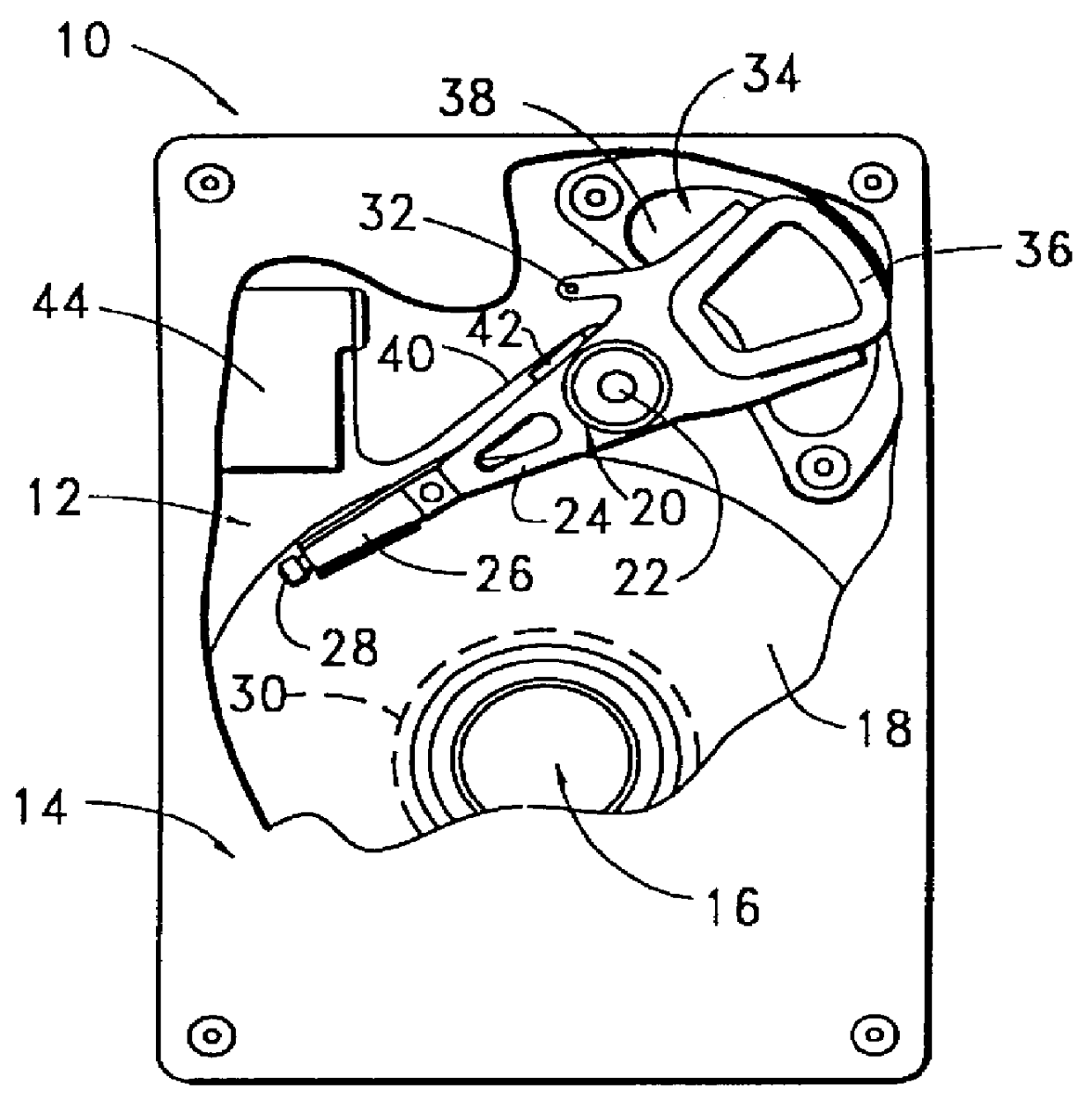
Turning now to the drawings and more particularly to FIG. 1, shown therein is a top plan view of a disc drive 10 constructed in accordance with the present invention. The disc drive 10 includes a base deck 12 to which various disc drive components are mounted and a top cover 14, which is shown in a partial cut-away fashion to expose selected components of interest. Although not explicitly illustrated in the top plan view of FIG. 1, it will be readily understood that the base deck 12 includes an interior surface to which various disc drive components are mounted as well as side walls which, in combination with the top cover 14, provide sufficient height to house these components within a sealed internal environment.

Mounted to the base deck 12 is a spindle motor (shown generally at 16) to which a plurality of discs 18 are mounted for rotation at a constant high speed. Adjacent the discs 18 is an actuator assembly 20 which pivots about a pivot bearing assembly 22 in a rotary fashion. T...


PUM


Abstract

PCT No. PCT/US97/04906 Sec. 371 Date Oct. 21, 1997 Sec. 102(e) Date Oct. 21, 1997 PCT Filed Mar. 27, 1997 PCT Pub. No. WO97/43835 PCT Pub. Date Nov. 20, 1997An apparatus and method for recovering from read errors detected by a read channel (70) in a sequence of data read from a disc (18) of a disc drive (10) by using read channel quality indicators to determine the appropriateness of using error correction in combination with other corrective actions utilized in the recovery process. Upon the detection of an uncorrected error in the retrieved data, the disc drive (10) enters a read error recovery routine wherein one or more corrective actions (102, 122) are applied in an effort to resolve the error. One of the channel quality indicators comprises a channel quality measurement (108, 128) determined as the sum of the square of the sampled data bit error values recovered during the read operation. When the channel quality measurement is at or below a threshold value indicative that the probability of passing undetected erroneous data is at an acceptable level (110, 130), error correction is applied to the data (112, 138); otherwise, error correction is disallowed (118, 140). Additional channel quality indicators comprise erasure pointers (132) which identify a particular set of symbols that are suspected of containing a read error. In such a case, the disc drive determines that the total number of symbols identified by the erasure pointers is below a predetermined erasure threshold before applying error correction (134, 136, 138), the erasure threshold selected to be within the correction capability of error correction circuitry 90.

Description

This invention relates generally to the field of disc drive data storage devices, and more particularly, but not by way of limitation, to a method and apparatus for improving read error recovery operations in a disc drive through the of read channel quality indicators.Disc drives are commonly used in workstations, personal computers, laptops and other computer systems to store large amounts of data in a form that can be made readily available to a user. Such drives store and retrieve data using one or more magnetizable discs that are rotated at a constant high speed by a spindle motor. Each of the discs has a magnetizable surface coating that can be selectively magnetized by a corresponding read / write head so that the data is stored in the form of magnetic flux transitions along defined data tracks on the surface of the disc.The heads are typically suspended over the discs and positionably controlled with respect to the tracks on the discs through the use of a rotary actuator assemb...

Claims


Application Information

Patent Timeline
IPC IPC(8): G11B27/36G11B19/04G11B20/18G11B5/09G11B5/012H03M13/00H03M13/15H03M13/35H03M13/45
CPCG11B5/012G11B19/04G11B20/10055G11B20/10481G11B20/18G11B20/1833G11B27/36H03M13/1515H03M13/154H03M13/3707G11B2220/20G11B5/09H03M13/00
Inventor GENHEIMER, STEPHEN R.SHAVER, JIMMIE R.
Owner SEAGATE TECH LLC
Why Eureka
Try Eureka