Phase-locked loop oscillator formed entirely of logic circuits

a logic circuit and phase-locked loop technology, applied in the direction of pulse generator, pulse automatic control, electric pulse generator circuit, etc., can solve the problems of difficult to keep the same electrical characteristics for such elements, the arrangement of the peripheral connection pads is not specialized, and the connection pads that are dedicated to them on the periphery of the chip are not special

Inactive Publication Date: 2000-04-04
SEXTANT AVIONIQUE
View PDF5 Cites 14 Cited by
  • Summary
  • Abstract
  • Description
  • Claims
  • Application Information

AI Technical Summary

Problems solved by technology

Various integration technologies, which are often mutually incompatible, are sharing the market at any given time.
Furthermore, the connection pads that are dedicated to them on the periphery of a chip are not specialized.
Indeed, it is then difficult to keep the same electrical characteristics for such elements during a change in integration technology.
Furthermore, there often rises a problem of the arrangement of the peripheral connection pads as these pads, in most cases, are specialized and have positions that vary with the integration technologies.

Method used


Image

  • Phase-locked loop oscillator formed entirely of logic circuits
  • Phase-locked loop oscillator formed entirely of logic circuits
  • Phase-locked loop oscillator formed entirely of logic circuits

Examples


Embodiment Construction

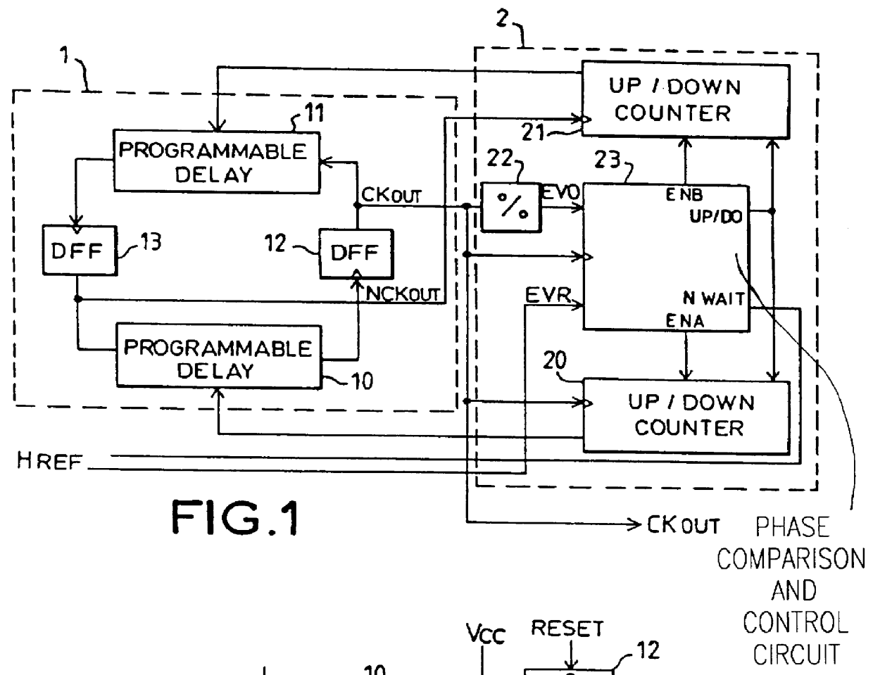
As can be seen in FIG. 1, the phase-locked loop oscillator consists of a frequency-tunable oscillator 1 made solely by means of logic circuits. This oscillator 1 is associated with a phase servo-control loop 2 also made solely by means of logic circuits.

The oscillator 1 delivers a clock signal CKOUT. The phase-locked loop 2 receives the signal CKOUT coming from the oscillator 1, divides it in frequency, compares it in phase with a reference signal HREF and then uses the result of the phase comparison to adjust the frequency of the oscillator 1.

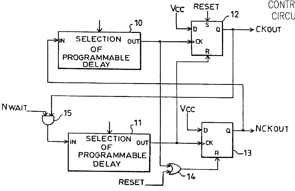
The frequency tunable oscillator 1 essentially has two programmable-delay transition propagation circuits 10, 11 looped together by means of two D type logic flip-flop circuits 12, 13. This oscillator 1 shall be described here below with reference to FIG. 2.

The phase-locked loop 2 consists chiefly of:

two up / down counters 20, 21 that deliver the values of the delays of the two programmable-delay transition propagation circuits 10, 11 of the osc...


PUM


Abstract

Phase-locked loop oscillators that are designed to set the clock rate of electronic circuits based on combinations of logic circuits and to be integrated, at the same time as these electronic circuits, into one and the same chip. There is proposed a phase-locked loop oscillator based purely on combinations of logic circuits so as not to make use of integration techniques different from those used for the electronic circuits based on combinations of logic circuits, for which they are designed to set the clock rate.

Description

1. Field of the InventionThe present invention relates to phase-locked loop oscillators and especially to those designed to generate the clock signals of an electronic circuit made on an integrated circuit chip.The performance characteristics obtained today by integration techniques enable the integration, on an integrated circuit chip, of electronic circuits based on complex combinations of logic circuits performing sequences of operations at very high rates, known as clock rates. These clock rates can no longer be distributed synchronously on printed circuit boards. This is because the time taken by the clock signals to travel from a single location to different locations of the integrated circuit chips and the dispersion between these travelling times are no longer negligible as compared with the period of these signals. This impossibility of achieving a synchronous distribution, on printed circuit boards, of the very high clock rates required by the electronic circuits integrate...

Claims


Application Information

Patent Timeline
Patent Type & Authority Patents(United States)
IPC IPC(8): H03L7/089H03L7/099H03L7/08
CPCH03L7/0995H03L7/089
Inventor PITOT, CHRISTIANPROST, MICHEL
Owner SEXTANT AVIONIQUE
Why Eureka
Try Eureka