Apparatus and method for clamping an image signal

an image signal and clamping technology, applied in the field of apparatus and clamping an image signal, can solve the problems of excessive delays, convergence generally takes the initial power-on procedure also requires a relatively long time, so as to achieve a high degree of stability and high degree of accuracy

Inactive Publication Date: 2000-04-11
SONY CORP
View PDF9 Cites 31 Cited by
  • Summary
  • Abstract
  • Description
  • Claims
  • Application Information

AI Technical Summary

Benefits of technology

Another object of the present invention is to provide a clamp circuit which carries out a linear feedback clamping operation with a high degree of stability as well as with a high degree of accuracy.
An additional object of this invention is to provide a clamping technique in which an image signal is converged in a relatively short time.

Problems solved by technology

When the image data signal is suppressed by suppressing the level variations thereof (which occur due to the flag signal) to converge the image data signal, such convergence generally takes a relatively long time.
Thus, the initial power-on procedure also requires a relatively long time.
Still further, convergence of the image data signal also takes a relatively long time when the level of the image data signal exceeds the reference level during an image pickup operation, thus resulting in excessive delays before an image can be picked up by the imaging device.

Method used


Image

  • Apparatus and method for clamping an image signal
  • Apparatus and method for clamping an image signal
  • Apparatus and method for clamping an image signal

Examples


Embodiment Construction

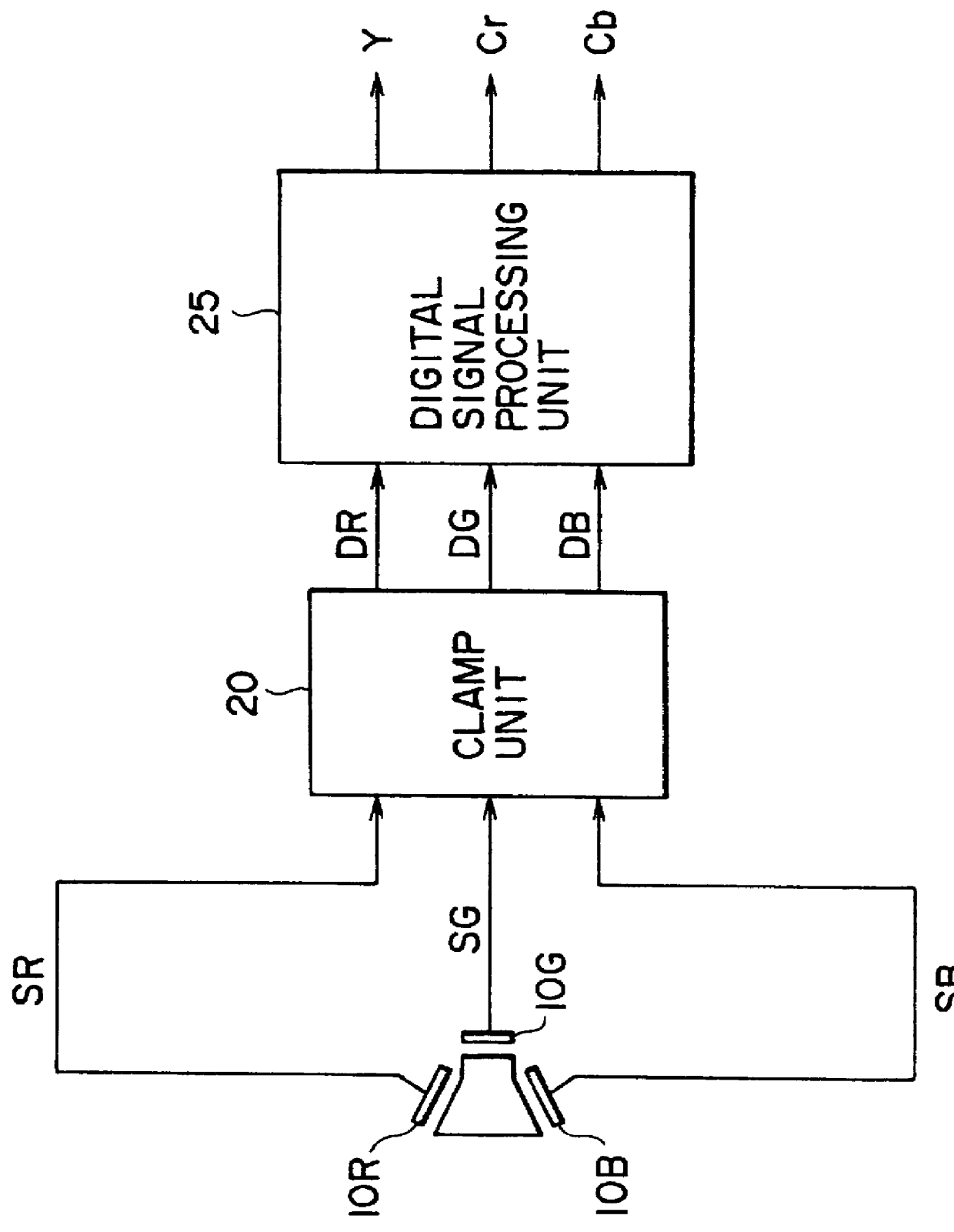
Referring now to the drawings, FIG. 1 is a block diagram of a video camera embodying the clamping circuit of the present invention. As shown, the video camera is comprised of three solid state image pickup devices, 10R, 10B and 10G (hereinafter, CCD image sensors), a clamp unit 20 and a digital signal processing unit 25. An image is picked up by the CCD image sensors, wherein CCD image sensors 10R, 10G and 10B produce image signals SR, SG and SB, respectively, corresponding to the three primary colors. Signals SR, SB and SG are supplied to clamp unit 20 which clamps the levels of the supplied signals to a predetermined level and which convert the clamped signals to respective digital image signals DR, DG and DB. Digital image signals DR, DG and DB are supplied to digital signal processing unit 25 which performs various processing on the digital signals including linear matrix processing, gamma correction, knee correction, etc., in a manner well known in the art, and also converts th...


PUM


Abstract

A clamping circuit for use in a video camera varies a level of an image signal utilizing an analog feedback control signal, converts the varied image signal to a digital image signal, generates a digital zone value signal that corresponds to a level of a reference zone of the digital image signal, digitally detects an amount of error between the digital zone value signal and a predetermined zone value having a non-zero fractional portion, generates from the detected amount of error a digital error signal that has a predetermined number of data bits, switches between a coarse adjustment mode and a fine adjustment mode of the clamping circuit in accordance with a level of the digital error signal, generates, in the coarse adjustment mode, a pulse width modulated signal from the most significant bits of the digital error signal, generates, in the fine adjustment mode, the pulse width modulated signal from the least significant bits of the digital error signal, and generates from the generated pulse width modulated signal the analog feedback control signal.

Description

The present invention relates to a video camera and, more particularly, to apparatus and method for clamping an image signal for use in a video camera.As is known, analog image signals output from image pickup devices are supplied to a feedback clamp circuit prior to being processed in various manners including, for example, linear mask processing, gamma correction, and knee correction, in order to produce a video signal. The feedback clamp circuit converts the analog image signal to a digital signal, generates an error signal from the difference between the digital signal and a digital-code signal representing a reference level, converts by means of integration the error signal to an analog signal, and adds the analog signal to the originally supplied image signal. The feedback clamp circuit operates to control the level of the analog image signal to a predetermined level. However, to provide linear feedback clamping with a high degree of accuracy, the generated error signal must h...

Claims


Application Information

Patent Timeline
Patent Type & Authority Patents(United States)
IPC IPC(8): H04N9/04H04N5/18H04N9/64H04N5/16H04N5/335H04N5/357H04N5/378
CPCH04N5/18H04N9/045H04N2209/049H04N9/64H04N5/185
Inventor KAMEYAMA, TAKASHI
Owner SONY CORP
Why Eureka
Try Eureka