Magnetically suspended high velocity vacuum pump

a vacuum pump and magnetosuspension technology, applied in the direction of bearings, shafts, liquid fuel engines, etc., can solve the problems of ductile shafts, long ductile shafts, and very concluding suspension of rotating parts

Inactive Publication Date: 2000-04-18
MAGNETAL
View PDF11 Cites 26 Cited by
  • Summary
  • Abstract
  • Description
  • Claims
  • Application Information

AI Technical Summary

Problems solved by technology

This leads to that the suspension of the rotating parts becomes very conclusive.
A disadvantage with such an arrangement is that if the pumps should obtain a certain compression ratio, they tend to be rather long.
The longer shaft, the more ductile shaft and the balancing becomes more difficult.
Even such systems require long shafts, which besides the above mentioned disadvantages also makes the pump heavy and ungainly.
A disadvantage with long shafts is, besides the high weight and that the pumps becomes bulky, that the critical number of revolutions for the shaft tends to be rather low, which limits the useful rotational speed for the pump.
If the bearing is of a mechanical type, there will arise problems with lubricating the bearing without destroying the high vacuum.
If the bearing is a contact free magnetic suspension, no lubrication is indeed not needed, but on the other hand are most magnetic materials somewhat porous and may thereby give rise to degassing problems.
This is a great drawback, in particular during venting of pumps in operation, when the forces may be very high.
The latter may not be made totally stable, but are often used together with a stabilising ball bearing, which then reduces their field of application.
The great disadvantage with such bearings, using the so called electrodynamic repulsion, has been that the bearing generates very much heat, i.e. given rise to unacceptably high energy losses.
Furthermore, the heat is difficult to cool away in high velocity vacuum pumps.
Furthermore, the speed has to be infinitely high.
The practical limitations are obvious.
Despite that the energy losses have been reduced significantly are the losses still too high to enable a commercial application of the bearings.
Even if the bearings suggested by Lembke by experimental trials have been proved to be proportionally good, especially considering axial suspension, radial bearings of this type nevertheless still result in problems.
For one thing because the thermoexpansion of the rotor has appeared to influence the losses considerably, since the rotor no longer is able to centre exactly between the magnets.
The basic reason for the disadvantages with magnetic bearings in high velocity vacuum pumps according to the state of the art is that the area where the field has "null flux", i.e. lacks any normal component, is infinitely thin by it self, why only an infinitely thin plate can be used.
If the plate exhibits a thickness, the surface layers will be exposed to a fluctuating magnetic field when the plate passes by the magnets, whereby unnecessary eddy currents arise.
The demand on the rotating plate to be thin is a drawback upon use in a high velocity vacuum pump.
The complex of problems concerning the thermo-expansion of the rotor also creates problems, since an efficient cooling is difficult to realise in a vacuum pump of this type.
This is a great drawback since the slits in the operating parts of the pump is requested to be as small as possible to prevent backstreaming of the gas.
Another disadvantage with high velocity vacuum pumps according to the state of the art is that it generally is impossible for a user to perform change of bearings or other advanced maintenance without access to advanced special tools.
This means that service normally can not be performed at site, but the pump unit has to be disconnected and sent away to the manufacturer or authorised service personnel for such measures.
Subsequently, the user is caused long inactivity periods and costs in connection with maintenance.

Method used


Image

  • Magnetically suspended high velocity vacuum pump
  • Magnetically suspended high velocity vacuum pump
  • Magnetically suspended high velocity vacuum pump

Examples


Embodiment Construction

Following, a number of embodiments of the present invention will be described by different exemplifying embodiments. However, it will be understood by someone skilled in the art that other variations falling within the scope of the present claims are possible.

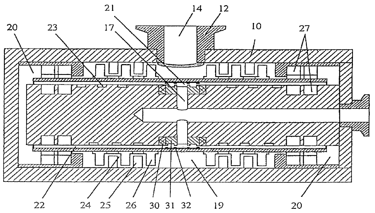
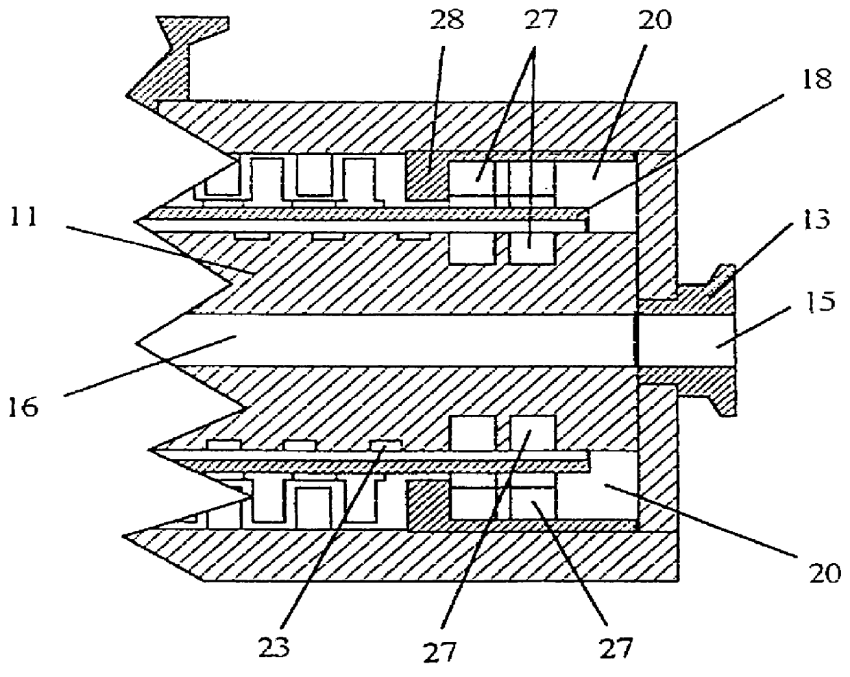
In FIG. 1, an embodiment of a high velocity vacuum pump according to the present invention is shown. A pump housing comprises an outer stationary casing 10, which hereafter is referred to as outer stator portion, and which encloses the operational pump parts. The stationary part of the pump further comprises en inner stator shaft, which among other things comprises an inverted motor (which is described separately below) and is firmly fitted at one end of the outer stator portion. The outer stator portion 10 further comprises two flanges, one high vacuum flange 12, fitted at the middle of the outer stator portion, and a forevacuum flange 13, fitted at one of the short sides of the pump housing. Through openings 14, 15 in these f...


PUM


Abstract

High velocity vacuum pump, such as turbomolecular pump, drag pump, centrifugal pump or the like, comprising a stator (10) and a rotor (18,43,53), which is axially and radially suspended with respect to the stator (10) by magnetic bearings (27). The vacuum pump may comprise two at the same rotor provided, parallelly acting pump portions, each one comprising two pumping steps. The rotor may be cylindrical and rotates around an inner stator shaft and within an outer stator portion. In that way, one pumping step (22) is formed between the inner stator shaft and the rotor and another pumping step (24) between the outer stator portion (10) and the rotor. The magnet bearing comprises at least one rotation symmetric magnet (27) and is disposed to give rise to a rotation symmetric magnetic field which is centered around the rotational axis. When and only when the rotor tends to leave the predetermined path, the magnetic field generates induced eddy currents in the rotor, which give rise to restoring stabilizing forces.

Description

The invention relates generally to a high velocity vacuum pump. By vacuum pumps is here understood turbo molecular pumps, drag pumps, centrifugal pumps and similar pumps operating at high rotational speed, and combinations thereof.PRIOR ARTHigh velocity vacuum pumps are used today in many high vacuum applications, when a high vacuum of best quality as well as when relatively large amounts of gas is intended to be pumped away. Turbo molecular pumps operates according to the principle that fast movable solid sections transfer a linear momentum to substances in gas phase which come in their path. The average velocity of the gas particles can in this manner be directed out from the volume which is requested to be evacuated. Drag pumps normally operate at a higher pressures and force, by means of friction against a rotating wall, gas into helical grooves. Different types of pumps can also be combined in several steps to give a higher compression. Common for all of these types is that the...

Claims


Application Information

Patent Timeline
Patent Type & Authority Patents(United States)
IPC IPC(8): F04D29/04F04D19/04F16C39/06F04D19/00F16C39/00F04D29/058
CPCF04D19/046F04D19/048F16C32/0438F16C32/0436F04D29/058F16C2360/45
Inventor LEMBKE, TORBJORN
Owner MAGNETAL
Why Eureka
Try Eureka