Methods and apparatus for welding performance measurement

a technology of performance measurement and welding equipment, applied in the field of welding, can solve the problems of ineffective process and inability to objectively measure the duty cycle of most arc welding management systems

Inactive Publication Date: 2000-04-18
AIR LIQUIDE CANADA
View PDF11 Cites 204 Cited by
  • Summary
  • Abstract
  • Description
  • Claims
  • Application Information

AI Technical Summary

Problems solved by technology

For continuous operations, such a process was not useful.
Most arc welding management systems do not objectively measure the duty cycle experienced by the overall welding operation at the manufacturing plant.
This is due to the unavailability of a suitable device and method that can be used without interrupting the manufacturing cycle, which would measure effectively the average amperage and the welding efficiency at the selected work station.

Method used


Image

  • Methods and apparatus for welding performance measurement
  • Methods and apparatus for welding performance measurement

Examples


Embodiment Construction

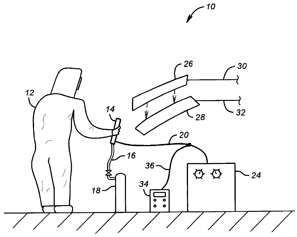
FIG. 1 illustrates schematically an arc welding station 10, the illustration being helpful to an understanding of the various aspects of the invention. An arc welder 12, here illustrated as human, although robotic welding machines are considered within the invention, holds an arc welding device 14 to which is attached tubing 16 which routes shielding gas from a cylinder or other source 18. Also illustrated schematically connected to the arc welding device 14 is a cable or electrical wire 20 which carries sufficient amperage from a power source 24 to effect the arc welding operation. The human or robot welder is illustrated in position to arc weld pieces 26 and 28 together, typically in a fillet weld, the pieces 26 and 28 being supported in FIG. 1 by fictitious supports 30 and 32, respectively. A performance arc time measurement apparatus of the invention is depicted at 34 and is attached via an electrically conducting wire or cable 36 to cable 20 which connects power source 24 to ar...


PUM

PropertyMeasurementUnit
diametersaaaaaaaaaa
diameteraaaaaaaaaa
weightsaaaaaaaaaa

Abstract

Methods and apparatus are provided for determining the duty cycle, average amperage, and/or the number of arc starts during a welding operation. The apparatus comprises first and second circuits, the first circuit being a CPU control circuit, and the second circuit being an arc time sensor circuit which is programmed to measure amperage, welding wire feed speed and preferably gas flow rates while welding. A ratio of the cumulative welding time during the audit to the total on-time provides a measurement of the efficiency of the welding arc. The welding deposition efficiency may then be calculated using the average amperage and welding duty cycle as measured and calculated by the apparatus. The number of arc starts where the arc on-time is in excess of one second may also provide a useable measurement in giving secondary information on the overall efficiency of the welding operation.

Description

1. Field of the InventionThe present invention relates generally to the field of welding. More specifically, the present invention relates to methods and apparatus designed to increase welding productivity of a manufacturing shop.2. Related ArtThe metal fabrication industry has been around for many years. After the first World War, the shielded metal arc process became very popular through the use of extrusion technology. For continuous operations, such a process was not useful. As a result, semiautomatic welding processes using continuous wire were developed in the 1960s to improve productivity. In the early 1970s, arc welding was a hot and dirty operation, using principally large diameter continuous consumable wires. As the technology to draw continuous consumable wire to smaller diameter became available in the early 1980s, the arc welding industry started using continuous consumable wire diameters as small as 0.030 inch for continuous welding. Today, both cored arc welding wires...

Claims


Application Information

Patent Timeline
Patent Type & Authority Patents(United States)
IPC IPC(8): B23K9/095
CPCB23K9/0953
Inventor VAIDYA, VIWEK V.CHASSE, CHRISTOPHER C.. L.
Owner AIR LIQUIDE CANADA
Why Eureka
Try Eureka