System and method for incubation and reading of biological cultures

a biological culture and incubation system technology, applied in the field of biological culture incubation and analysis, can solve the problems of reducing the number of doors reducing the number of times any and reducing the time of any single door to the external environment. , the effect of reducing the amount of time a single door is open to the external environmen

Active Publication Date: 2021-06-22
BD KIESTRA BV
View PDF10 Cites 0 Cited by
  • Summary
  • Abstract
  • Description
  • Claims
  • Application Information

AI Technical Summary

Benefits of technology

[0018]In an alternate embodiment, the incubator may also include a waste removal station that includes a waste removal outlet separate from the three doors in the face of the incubator. In this regard, the waste removal station includes a waste transportation element for transporting a container marked for removal to the waste removal station via the waste removal outlet. By providing a separate waste removal outlet the removal of the waste containers from the incubator can be performed such that it does not interfere with the discharge of useful containers from the incubator via the second door. In this regard, the throughput of containers is increased even further. In addition by providing a separate waste removal outlet the removal of containers from the incubator can reduce the risk of incubator contamination and contamination of other specimen containers. Additionally, the waste removal outlet helps to maintain the controlled environmental conditions within the incubator.
[0020]Having at least three separate access / egress points for the sample containers to enter into and be removed from the incubator cabinet provides many advantages to automated incubator operation. Examples of such advantages include streamlined operation due to separate conveyor tracks for separate functions, enhanced preservation of incubator environment because the amount of time any single door is open to the external environment is reduced compared with configurations with fewer doors and comparable capacity and functionality. Moreover, having the image capture module directly adjacent to the incubator reduces the amount of time the sample container is exposed to an external environment (with its lack of precisely controlled temperature and atmosphere and potential contaminants) while the sample container is imaged. Since the image capture module is enclosed, it acts as a shield between the lab atmosphere and the incubator atmosphere reducing the extent to which the lab atmosphere enters the incubator and the sample containers enter from the incubator and return thereto through the third door.

Problems solved by technology

One problem with incubators is the difficulty in maintaining the controlled atmosphere when samples are retrieved from the incubator.
One challenge for incubators with controlled atmospheres is maintaining the controlled atmosphere when the sample is inserted, removed from or replaced into the incubator as the sample is evaluated to determine the presence of absence of microorganisms in the sample.
This results in a significant loss of the incubator's controlled atmosphere to the larger environment, typically a laboratory environment, in which the incubator is placed.
The loss of the controlled environment in the incubator enclosure can retard microbial growth in the culture media or contaminate the specimen.
Additionally, removing the sample containers from the incubator for an extended period of time, for example to electronically image the sample culture to detect microbial growth, could negatively impact the growth of the target microorganisms or expose the specimens to contaminants in the lab, which can adversely affect the integrity of the assay results.

Method used


Image

  • System and method for incubation and reading of biological cultures
  • System and method for incubation and reading of biological cultures
  • System and method for incubation and reading of biological cultures

Examples


Embodiment Construction

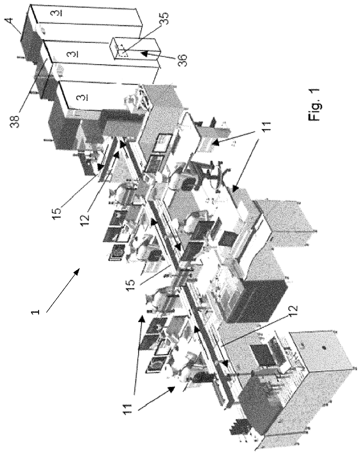
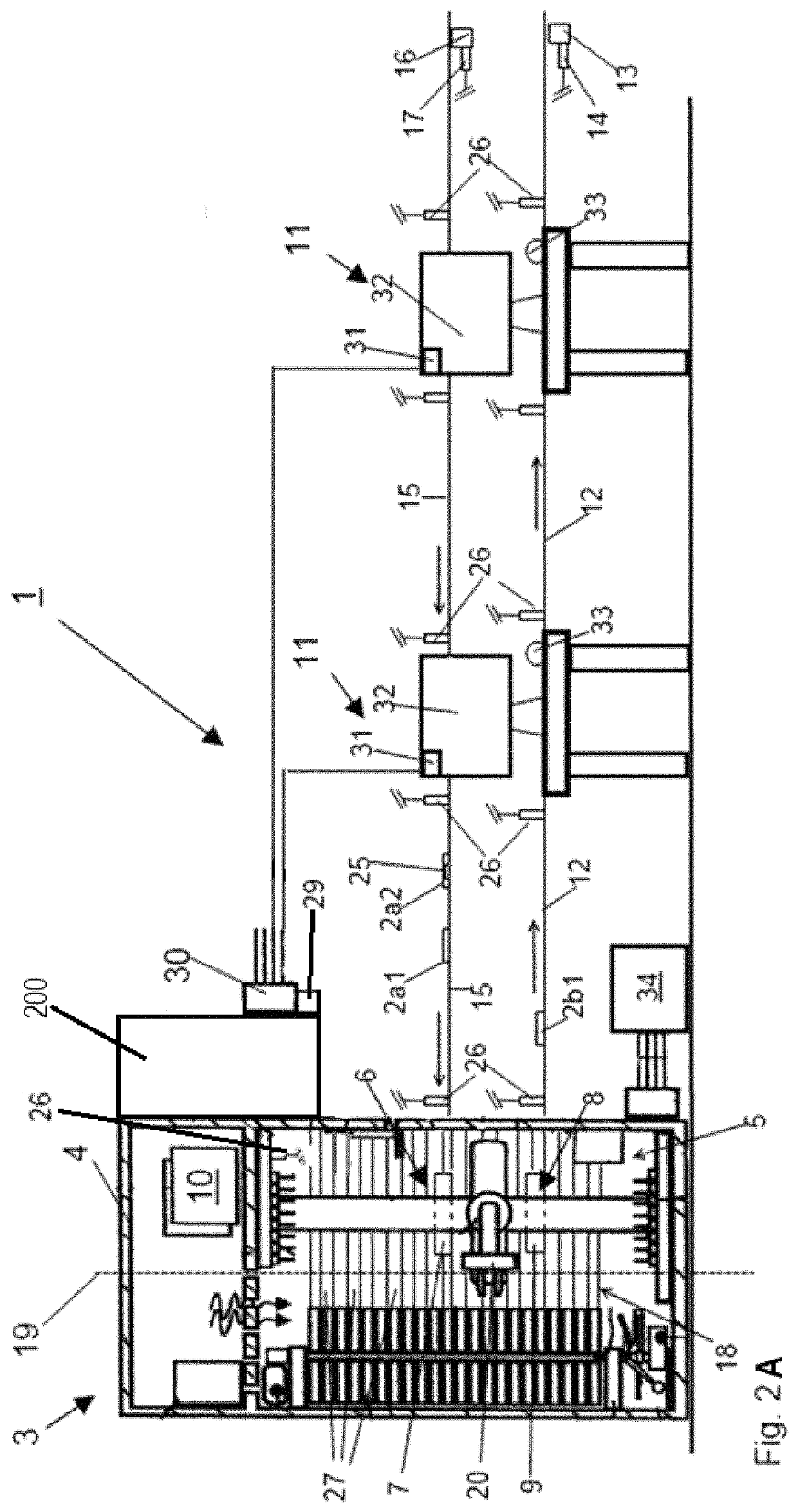
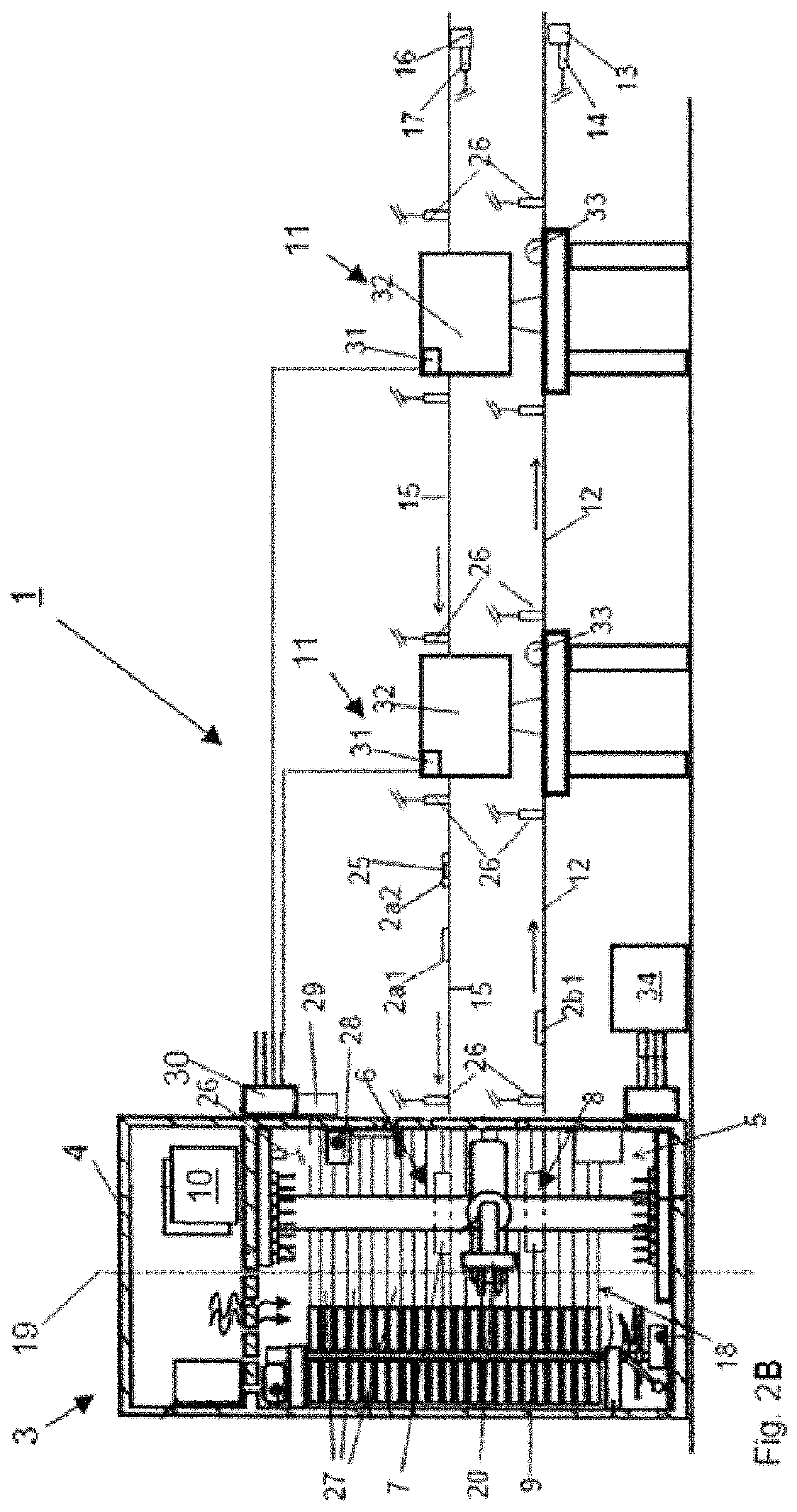
[0040]FIGS. 1, 2A, and 2B illustrate a perspective view and schematic representation of different embodiments of a system 1 for automated management of sample containers such as plated media according to the present invention is shown. The system 1 includes at least one integrated incubator and image capture module 3. The integrated incubator and image capture module 3 includes a housing 4 having an incubation chamber 5 that controls environmental conditions such that inoculated containers 2 can be cultured in a controlled manner. The integrated incubator and image capture module 3 as illustrated in FIGS. 1 and 2 also includes a loading station 6 having a first door 7 for receiving inoculated containers 2a into the incubation chamber 5. In the illustrated embodiment, a discharge station 8 having a second door 9 separate from the first door 7 is provided to allow for the discharge of incubated inoculated containers 2b from the incubation chamber 5.

[0041]As seen from the embodiment sh...


PUM

PropertyMeasurementUnit
incubation timeaaaaaaaaaa
sizesaaaaaaaaaa

Abstract

The present invention describes an integrated incubator and image capture module that regulates the incubator atmosphere and obtains high-resolution digital images of sample specimens. The incubator has a cabinet type enclosure that enables the provision of a controlled environment to the contents of the incubator by having at least three ports on one face of the cabinet for the passage of sample containers. Additionally, an image capture module is located immediately adjacent to the incubator. In this regard, using at least three separate access / egress points for the sample containers streamlines operation of the system and enhances preservation of the incubator environment. Furthermore, locating the image capture module directly adjacent to the incubator reduces the amount of time a sample container is exposed to the external environment, thereby reducing the extent to which samples are exposed to potential contaminants and reducing the exchange of the lab and ambient atmospheres.

Description

CROSS-REFERENCE TO RELATED APPLICATIONS[0001]The present application claims the benefit of the filing date of U.S. Provisional Patent Application No. 61 / 980,272 filed Apr. 16, 2014, the disclosure of which is hereby incorporated herein by reference.BACKGROUND OF THE INVENTION[0002]Field of the Invention[0003]The present invention relates to a method and system for incubating and analyzing biological samples.[0004]Description of the Related Art[0005]Sample incubators are used to grow and maintain microbiological and cell cultures prepared from biological samples for research and analysis in a number of fields. The simplest incubators are insulated boxes that work by controlling a number of environmental factors, including temperature and humidity to provide an environment suitable to maintain sample viability and / or to support microbial growth. Incubators also have features that control the composition of the atmosphere in the incubator, such as the amount of carbon dioxide and / or ox...

Claims


Application Information

Patent Timeline
Patent Type & Authority Patents(United States)
IPC IPC(8): C12M1/00C12M1/12C12M1/26G01N35/04G01N35/00C12M1/36C12M3/00G01N35/02
CPCG01N35/04C12M23/44C12M41/14C12M41/48G01N35/0099G01N35/00732G01N35/0092G01N35/028G01N2035/00277G01N2035/00287G01N2035/00316G01N2035/00356G01N2035/00831G01N2035/00851G01N2035/0405G01N2035/0427G01N2035/0441G01N2035/0465G01N2035/0493G01N2035/0496
Inventor KLEEFSTRA, MARTIJNBERNTSEN, MARTIJN XANDERVAN DER VIJVER, JAN BARTNAUTA, TSJERKGIRGENSON, ANDREJ
Owner BD KIESTRA BV
Why Eureka
Try Eureka