Rotary electric machine, especially an alternator for a motor vehicle

a technology of motor vehicles and electric machines, applied in the field of rotating machines, can solve the problems of increasing the axial length of the alternator, increasing the manufacturing cost, and using the approach to the detriment of the output of the machin

Inactive Publication Date: 2000-04-18
VALEO EQUIP ELECTRIC MOTEUR
View PDF10 Cites 45 Cited by
  • Summary
  • Abstract
  • Description
  • Claims
  • Application Information

AI Technical Summary

Benefits of technology

Accordingly, the present invention provides an electrical machine comprising a stator and a rotor, the stator comprising on its internal face at least one induction winding housed in a pair of recesses and also comprising a series of housings for excitation means. The rotor possesses no windings and comprises a plurality of teeth adapted to selectively establish variable magnetic fluxes in the induction windings and the excitation means comprise at least one permanent magnet adapted to establish a magnetic flux looping round itself in a circumferential direction of the stator, and at least one excitation winding adapted to establish locally an adjustable magnetic flux in the reverse circumferential direction to that of the flux produced by the magnet or magnets, wherein the teeth of the rotor are adapted to effect a flux commutation in the stator and in that the, or each, permanent magnet occupies an angular position located between the angular positions of the two arms of a common induction winding so as produce an alternating magnetic flux in the induction winding or windings during the rotation of the rotor.

Problems solved by technology

The use of brushes, however, causes disadvantages, including an increase in axial length of the alternator, the need for an assembly of brushes and collectors which increases the manufacturing cost, and the risk of operating faults caused by a lack of contact between the brushes and the collector rings, usually caused by wear.
However, this approach is used to the detriment of the output of the machine, because the air gap surfaces are then very substantially decreased.
Moreover, a machine of this type, for a given output / speed curve, is substantially heavier than a conventional machine, and this is particularly disadvantageous in the case of alternators installed in vehicles.
This known solution to the problem also has disadvantages, caused in particular by the fact that the axial size of the machine is necessarily increased as well as its weight.
Moreover, the increase in size of the air gaps near the rotor decreases the output of the machine.
This necessity for a three-dimensional design of the machine makes the modelling and optimization of the different parameters extremely difficult and tedious.
This known structure has, however, certain disadvantages when it is excited either solely by magnets or by magnets associated with excitation windings.
In particular, in the first case the fact that the magnetic flux from which the induction current is produced is obtained solely from permanent magnets does not allow any control of the excitation of the machine.
Such machines can therefore serve only with difficulty as alternators of automobile vehicles, the speed of rotation of which may be extremely variable.
Taking into account the large currents involved, this solution results in a bulky device and much work is required for its production.
Moreover, regulation of the stator current is not advantageous from the energy balance point of view, because it implies dissipation as a pure loss of part of the electric power produced by the alternator.
Because the excitation current, is in this type of machine, by nature a bi-directional alternating current, such commutation requires the use of an "H" shaped commutation bridge, which is expensive.
Furthermore, if it is intended to combine this magnetic excitation flux created by permanent magnets with a complementary excitation flux created by windings, then there are problems in obtaining a zero, or substantially zero, induction current which is desirable especially during a cut-off of voltage to the electrical equipment supplied by the alternator.
The iron is thus used in a non-optimal manner: at the same saturation limit, the variation in useful flux is reduced in a ratio of about 1.15 to 1.2 relative to conventional flux commutation machines, which makes it necessary to add more induction conductors and so to increase the size of the machine.

Method used


Image

  • Rotary electric machine, especially an alternator for a motor vehicle
  • Rotary electric machine, especially an alternator for a motor vehicle
  • Rotary electric machine, especially an alternator for a motor vehicle

Examples


Embodiment Construction

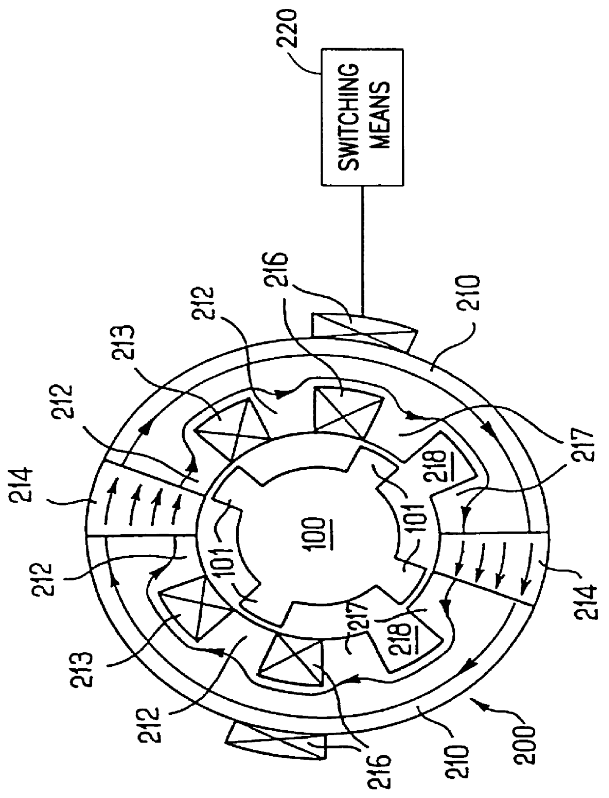
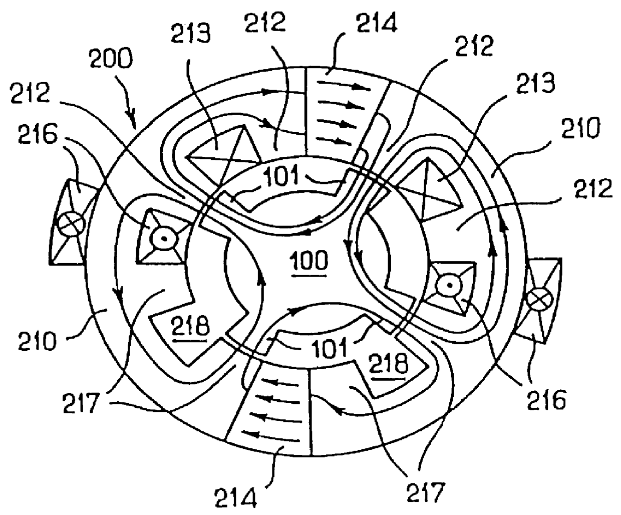
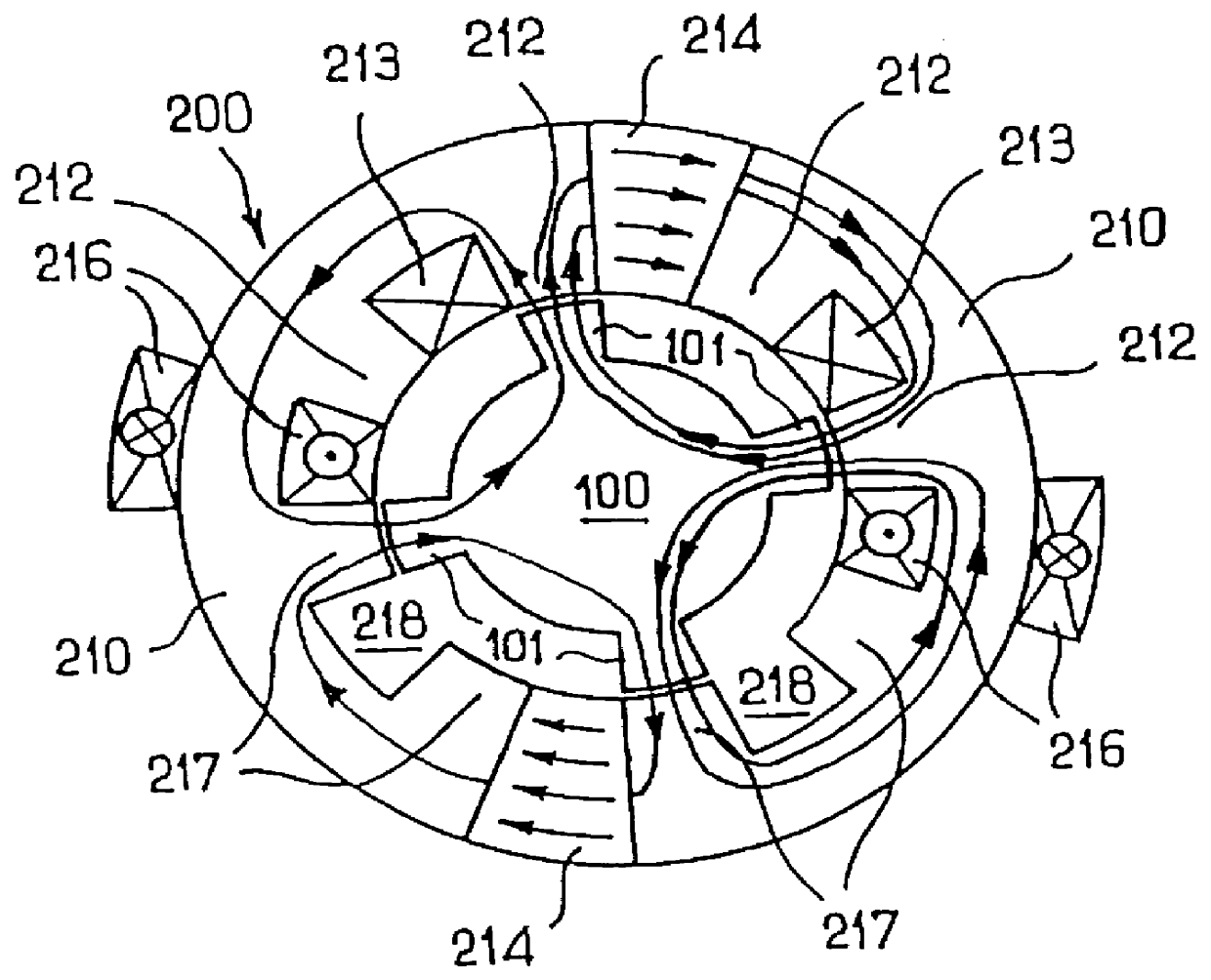
Referring first to FIGS. 1, 2a and 2b, these show a stator and a rotor which can be fitted to a single-phase flux commutation electrical machine in accordance with the invention.

The rotor 100 comprises on its periphery a plurality of projecting rotor teeth 101, in this particular case four in number, which preferably are evenly spaced at 90.degree. to one another. As will be seen later, the teeth 101 have the role of flux commutation when the machine is excited.

For its part the stator 200 comprises an annular body 210 consisting of two parts which define, conjointly with two diametrically opposed permanent magnets 214, a continuous annular structure. In the internal periphery of the structure, and more particularly in the two parts of the body, a plurality of recesses are formed, in this case two groups of three recesses. The recesses may or may not be regularly spaced. In a clockwise direction starting from one of the permanent magnets (in this case that at the top of the Figure) t...


PUM


Abstract

An electrical machine includes a stator and a rotor. The stator includes on its internal face at least one induction winding housed in a pair of recesses and a series of housings for excitation means. The rotor does not have windings and includes teeth for establishing variable magnetic fluxes in the induction winding. The excitation brings into play permanent magnets adapted to establish a closed circumferential magnetic flux in the stator and excitation windings locally establishing an adjustable magnetic flux in the reverse circumferential direction. The rotor teeth are adapted to effect a flux commutation in the stator and the, or each, permanent magnet occupies an angular position located between the angular positions of the two arms of a common induction winding. In this way an alternating magnetic flux is produced in the induction winding or windings during the rotation of the rotor.

Description

The present invention relates generally to rotary electric machines such as alternators for automobile vehicles.The polyphasic generator which comprises a conventional alternator for an automobile vehicle usually consists of a stator inside which a rotor equipped with an excitation winding rotates. The winding is supplied with current through contact brushes in contact with two collector rings provided on a projecting part of the rotor shaft.The use of brushes, however, causes disadvantages, including an increase in axial length of the alternator, the need for an assembly of brushes and collectors which increases the manufacturing cost, and the risk of operating faults caused by a lack of contact between the brushes and the collector rings, usually caused by wear.There are some proposals in the art which envisage the use of rotary electric machines, able to act as automobile vehicle alternators, which do not incorporate brushes.Thus an alternator is known in which the gripping devic...

Claims


Application Information

Patent Timeline
Patent Type & Authority Patents(United States)
IPC IPC(8): H02K21/44H02K21/00H02K1/17H02K19/24H02K1/24H02K21/04
CPCH02K21/44
Inventor AKEMAKOU, DOKOU ANTOINE
Owner VALEO EQUIP ELECTRIC MOTEUR
Why Eureka
Try Eureka