Chip forming cutting insert with internal cooling

a cutting insert and chip technology, applied in the field of chip forming cutting inserts with internal cooling, can solve the problems of limited cooling medium effect, cutting inserts subject to plastic deformation, cutting edges only exposed to cooling medium to a very limited degree, etc., to achieve efficient cooling, improve cutting inserts, and eliminate insert drawbacks

Inactive Publication Date: 2000-04-25
SANDVIK INTELLECTUAL PROPERTY AB
View PDF13 Cites 145 Cited by
  • Summary
  • Abstract
  • Description
  • Claims
  • Application Information

AI Technical Summary

Benefits of technology

The aim of the present invention is to eliminate the drawbacks of inserts with an internal coolant supply for chip removing machining as mentioned above and create an improved cutting insert. One basic purpose with the invention is thus to create a cutting insert which can be cooled efficiently without the assistance of open channels or grooves which run the risk of being clogged by chips. Another aim is to create a cutting insert which can be cooled efficiently by an internal supply of cooling medium without the mechanical strength of the cutting insert being significantly reduced and without the external geometry of the cutting insert, e.g., the chip breaking geometry, being limited because of the means necessary for the supply of cooling medium. A further purpose is to create a cutting insert which allows an efficient steering of the flow of cooling medium to the immediate vicinity of the edge without weakening or deteriorating the surface which is exposed to direct mechanical load from the chips in comparison to conventional, externally cooled cutting inserts. A further purpose is to create a cutting insert which, despite efficient cooling of the cutting edge of the cutting insert, does not require anything more than limited amounts of cooling medium.

Problems solved by technology

When large cutting forces act on the cutting insert this phenomenon entails a risk that the cutting insert will be subject to plastic deformation in particular in the proximity of the cutting edge, whereby insert breakage can result.
This method of supply, however, results in only a very limited amount of the cooling medium having any practical effect on the cutting insert.
That is, because of the presence of the chips, the cutting edge is only exposed to the cooling medium to a very limited degree.
However, when the cooling liquid is applied at normal pressures this procedure does not result in any significant improvement in cooling effect compared to the aforementioned methods because the cooling liquid does not reach that part of the cutting insert which is hottest and which is exposed to the greatest mechanical load.
Thus, a clear risk exists of the cutting insert becoming plastic because of excessively high temperature.
The effect of the cooling can certainly be increased considerably by increasing the pressure of the cooling liquid to very high levels, e.g., 250-300 Mpa, but the equipment required to raise the cooling liquid pressure to this level is very complicated and expensive.
Working with extremely high fluid pressure is furthermore, in practice, associated with appreciable safety risks.
Common to all the solutions to the problem indicated above, which are based on transverse or open channels or grooves for feeding the cooling medium, is that the channels weaken the cutting insert in the cutting edge area and there is a risk that the channels will be blocked by the hot material of the chip which sticks to the insert surface.
Furthermore, the existence of the channels or grooves limits the possibilities to design the cutting insert with an optimal chip breaker geometry.
However, this cavity weakens the cutting insert to such a large degree that its use is not practical when exposed to typical cutting forces.

Method used


Image

  • Chip forming cutting insert with internal cooling
  • Chip forming cutting insert with internal cooling
  • Chip forming cutting insert with internal cooling

Examples


Embodiment Construction

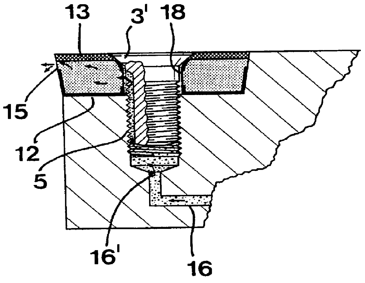
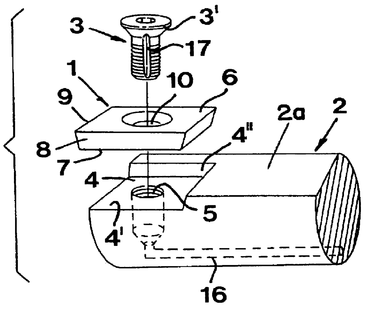
In FIG. 1 a cutting insert 1 according to the invention is being assembled in a holder 2. In the example shown this is achieved with the help of a clamping screw 3. The cutting insert holder 2, of which only a forward part is illustrated in FIG. 1, has the form of a shank which has cylindrical basic form with the exception of a planar side surface 2a. At the forward end of the planar surface 2a an insert seat 4 is formed which is bordered by a bottom surface 4' and two side faces 4" positioned at an acute angle relative to a plane of the bottom surface 4'. The cutting insert 1 has a central, transverse hole 10 for the clamping screw 3, which is provided to be screwed down into a threaded hole 5 disposed in the bottom surface 4'.

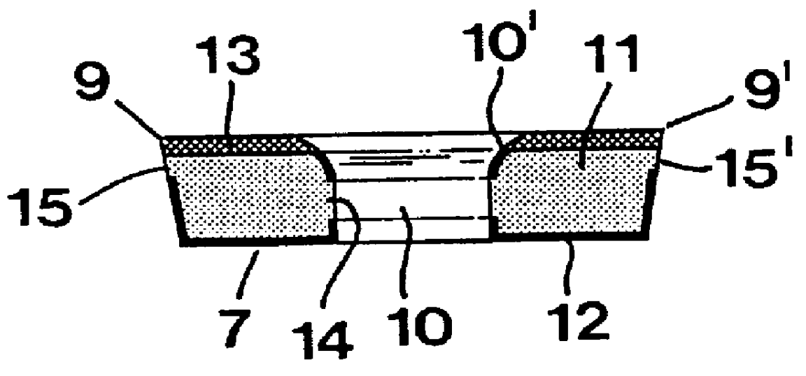
Generally, the cutting insert 1 is limited by an upper surface 6, an under surface 7 (see FIG. 2) as well as four side faces 8 which extend between the upper surface and the under surface. In the embodiment taken as an example, the cutting insert has a positi...


PUM

PropertyMeasurementUnit
total thicknessaaaaaaaaaa
temperatureaaaaaaaaaa

Abstract

A cutting insert is cooled during chip removing machining of a workpiece by conducting cooling medium through a porous supporting body of the insert. The cooling medium enters the insert through an inlet formed therein at a location remote from a cutting edge of the insert and exits the insert through an outlet formed in the insert at a location proximate the cutting edge. The discharged cooling medium impinges on, and cools, the workpiece.

Description

This invention refers to a cutting insert with internal cooling and intended for chip removing machining, the insert having an upper side, an underside and one or more side faces which extend therebetween and which includes at least one cutting edge in the area of the upper side and in addition a clearance surface connected to the cutting edge which at least partially forms a side surface and on the other hand means by which a cooling medium can be guided in a direction towards the cutting edge in order to cool that edge.Prior ArtCutting inserts for chip removing machining become heated under the machining operations which causes the heat to quickly spread through the cutting insert. The cutting insert, which generally consists of cemented carbide, therefore reaches, in a very short time, a range of temperatures within which the resistance to plastic deformation of the cutting insert material decreases. When large cutting forces act on the cutting insert this phenomenon entails a ri...

Claims


Application Information

Patent Timeline
Patent Type & Authority Patents(United States)
IPC IPC(8): B23B27/00B23B27/10B23B27/16
CPCB23B27/10Y10T407/14Y10T407/28Y10T407/116Y10T407/27B23B2200/283B23B2250/12
Inventor LAGERBERG, STIG
Owner SANDVIK INTELLECTUAL PROPERTY AB
Why Eureka
Try Eureka