Electric motor

a technology of electric motors and motor rotors, applied in the direction of windings, mechanical energy handling, magnetic circuit shapes/forms/construction, etc., can solve the problems of large gap between magnets mounted on motor rotors and sensing devices, and the dependence of control system cost,

Inactive Publication Date: 2000-04-25
NGAI KEUNG METAL & PLASTIC MANUFACTORY +1
View PDF11 Cites 14 Cited by
  • Summary
  • Abstract
  • Description
  • Claims
  • Application Information

AI Technical Summary

Problems solved by technology

Furthermore, by controlling DC motors accurately they can overlap with many of the applications of stepper motors.
The cost of the control system depends on the accuracy of the feedback and the speed of the processor.
However, they all have their own disadvantages.
For Hall effect sensors, in practice the gap between a magnet that is mounted on the motor rotor and the sensing device is often too large for accurate and reliable results.
A disadvantage of forming one winding with fewer turns than the other windings is that a mechanical imbalance is introduced.
This mechanical imbalance inevitable introduces a number of difficulties and problems, including noise and excessive wear on the rotor bearings.

Method used


Image

  • Electric motor
  • Electric motor
  • Electric motor

Examples


Embodiment Construction

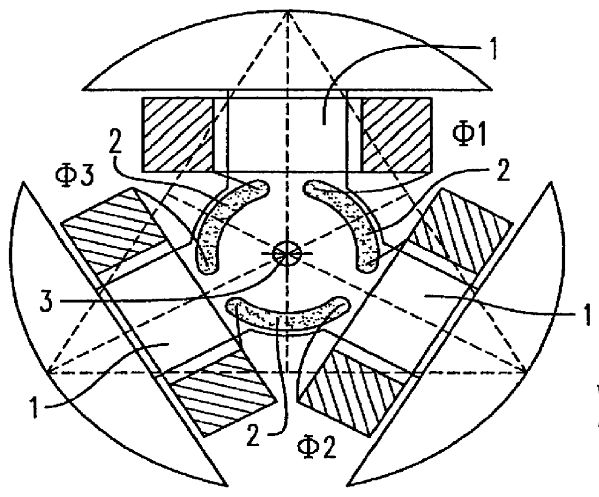
FIGS. 1A and 2A show a conventional electric motor. As described above the rotor of the motor comprises three equiangularly spaced poles 1 about each of which is an identical coil winding .PHI.. Each of the coil windings are connected between pairs of commutator segments 2 and as the rotor rotates bringing different pairs of commutator segments 2 into contact with the brushes (not shown in FIGS. 1 and 2), current is caused to flow through each winding in turn, the actual current depending on the applied DC voltage, the number of turns of the winding and the back emf generated. The current can be detected by including a tap resistance R in series and by taking a tap T as will be described further below.

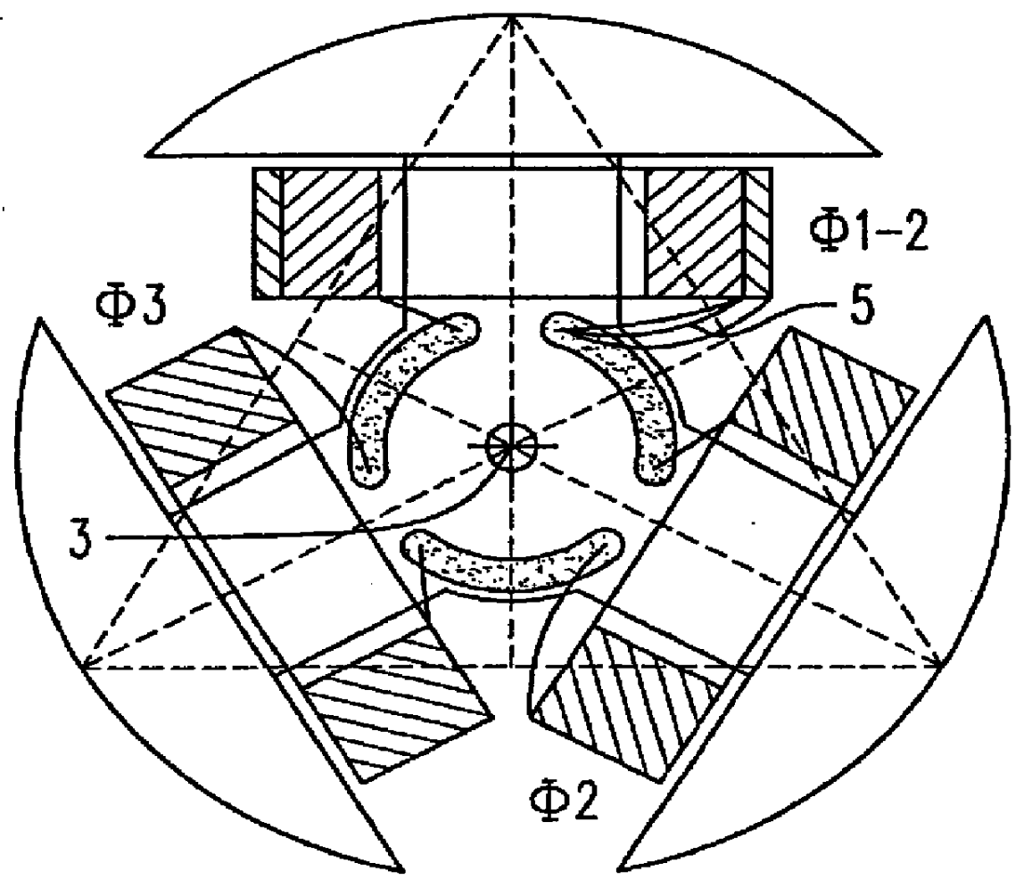
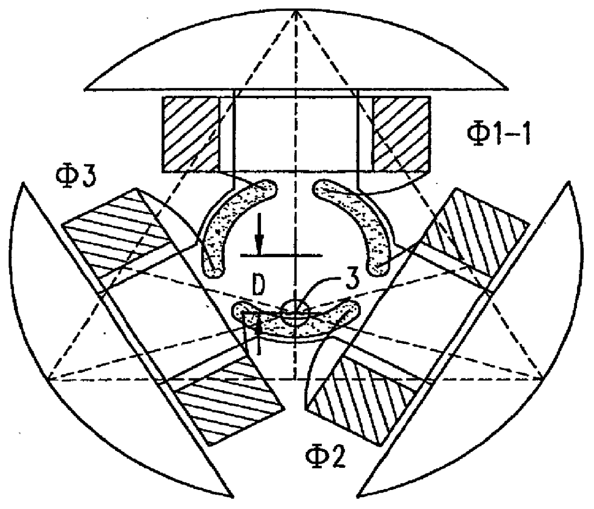
As shown in FIGS. 1B and 2B it is known to form one of the three windings .PHI.1-1 with a reduced number of turns in comparison with the other windings .PHI.2 and .PHI.3. This means that the current that flows when winding .PHI.1-1 is in the circuit is different from when either windin...


PUM


Abstract

The present invention provides an electric motor with a reduced number of windings on one of the coil windings. The effect of this is that when the motor is in operation, the current that flows through the coil with the reduced number of windings differs from the others, and this difference can be detected to allow accurate control of the motor. To avoid any mechanical imbalance caused by this difference in the number of windings, mechanical compensation means is provided on the arm with the reduced number of windings. Preferably this comprise a further winding that is not electrically connected to the motor circuit.

Description

This invention relates to an electric motor, and in particular to an electric motor of the type having one winding that differs from the other windings.BACKGROUND OF THE INVENTION AND PRIOR ARTDC motors are widely used in many industrial and consumer applications. In many cases absolute precision in movement is not an issue, but precise speed control often is. An example of this would be the drive motor of a cassette player. The cassette player is expected to run at a constant speed and so speed control is important, but the motor does not have to run for precise increments which are fractions of a turn, or to stop at a certain point.However, some motor applications do require precise positioning. For example, the motors used in high resolution plotters, disk drives, and robotics must all be carefully and precisely controlled in terms of position. There are also a number of applications that require both precise speed control and some position accuracy. Video recorders, compact disc...

Claims


Application Information

Patent Timeline
Patent Type & Authority Patents(United States)
IPC IPC(8): H02K7/00H02K7/04H02K23/66H02K23/26
CPCH02K7/04H02K23/66H02K23/26
Inventor CHIU, ANDREW SHUN PUI
Owner NGAI KEUNG METAL & PLASTIC MANUFACTORY
Why Eureka
Try Eureka