Shift controls for automated shifting manual transmissions with range sensing redundancy

a technology of automatic shifting and manual transmission, applied in the direction of gearing control, mechanical equipment, transportation and packaging, etc., can solve the problem of driver observing the error signal

Inactive Publication Date: 2000-05-02
FORD GLOBAL TECH LLC
View PDF24 Cites 34 Cited by
  • Summary
  • Abstract
  • Description
  • Claims
  • Application Information

AI Technical Summary

Benefits of technology

The invention provides improved protection, using three-bit separation between the bits of valid codes, against an unintended change in the direction of torque delivery in the transmission due to a range sensing switch failure. It does this by identifying when a range change is being commanded by the driver even when a single-point sensing switch failure is present. It will identify also when a range change is not being commanded by the driver, even when a fault condition is present due to a single-point sensing switch failure. Continued normal operation of the control system can be obtained following the early warning of a single-point switch failure.

Problems solved by technology

Transient error signals might be obtained indicating failure of a range sensing switch when an intermittent failure condition has occurred.
An error signal will be observed by the driver, however, only if the total number of error codes in a given time interval exceeds a calibrated threshold number.

Method used


Image

  • Shift controls for automated shifting manual transmissions with range sensing redundancy
  • Shift controls for automated shifting manual transmissions with range sensing redundancy
  • Shift controls for automated shifting manual transmissions with range sensing redundancy

Examples


Embodiment Construction

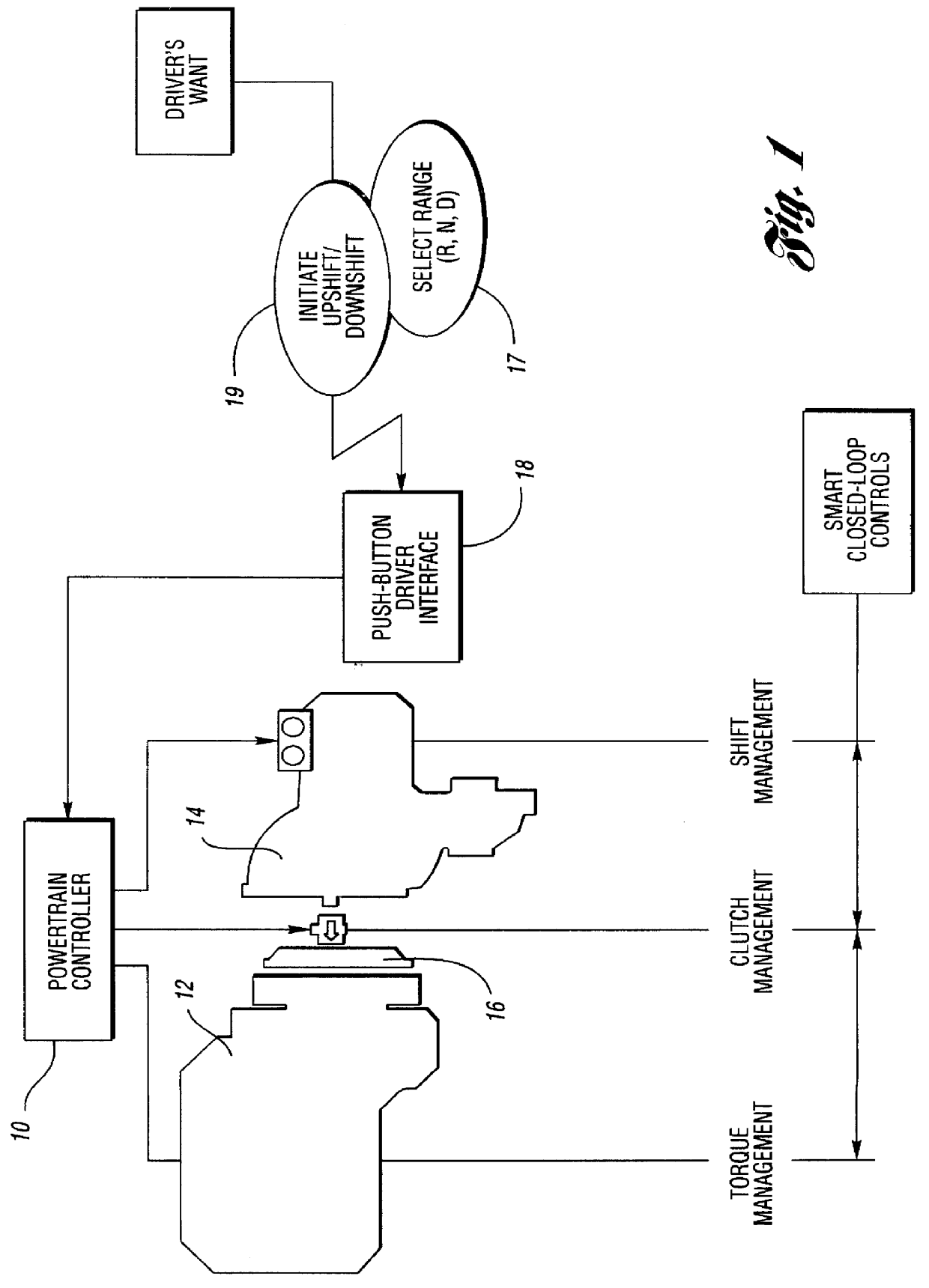
A system overview is shown in FIG. 1. It includes an engine and transmission electronic powertrain controller 10 for a vehicle engine 12 and a manually controlled transmission 14. A neutral clutch 16 establishes a driving connection between the crankshaft of the engine 12 and the torque input shaft of the transmission 14. The controller 10 establishes torque management for the engine, clutch management for the clutch 16 and shift management for the transmission 14.

A push-button assembly 18 establishes a driver interface with the engine and transmission powertrain controller 10. Range selection is made at 17 and upshifts and downshifts with selected range "D" are made at 19.

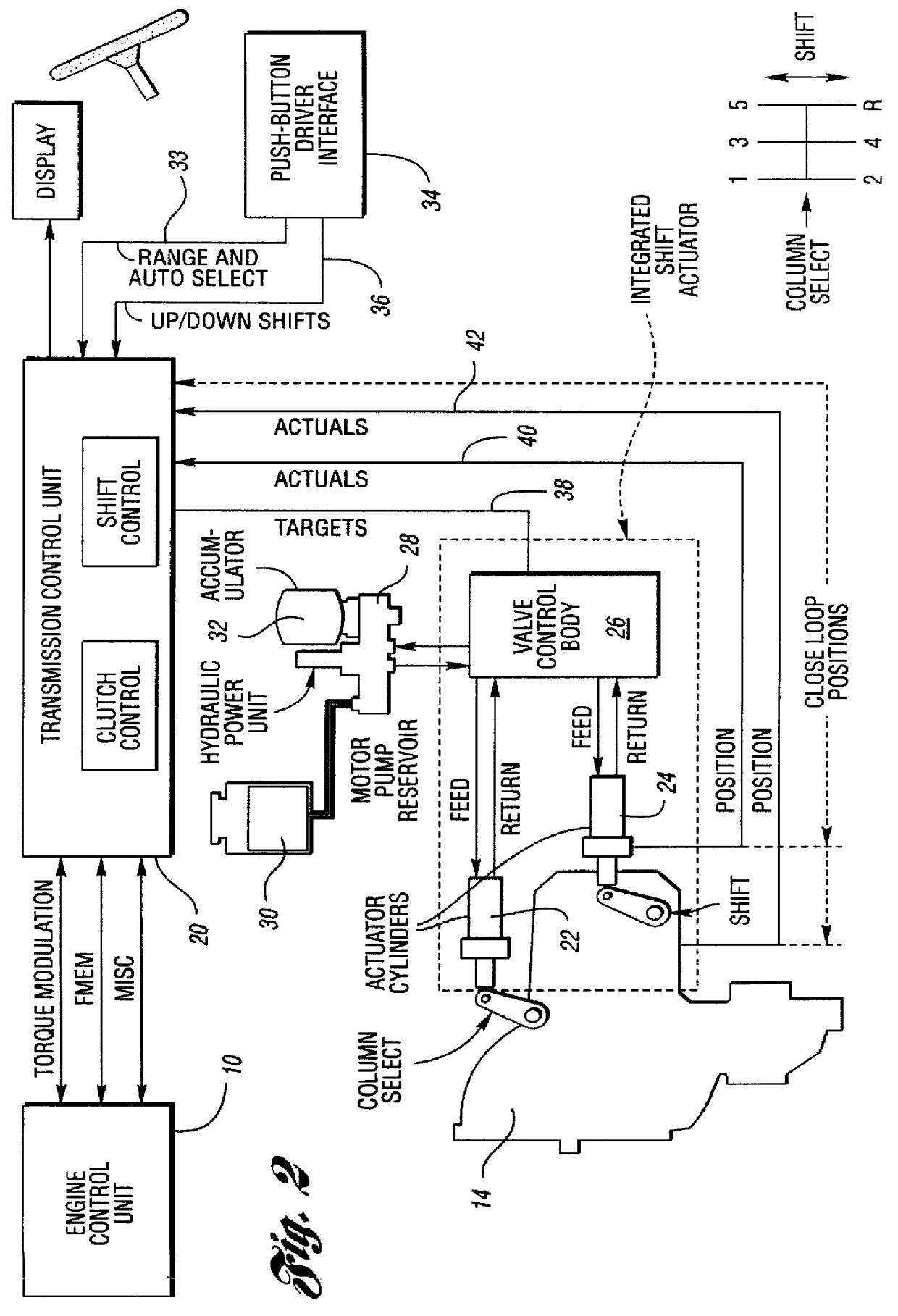
FIG. 2 shows the portion of the control system that is devoted to shift management.

The transmission control unit 20, for purposes of the shift management system illustrated in FIG. 2, includes a transmission module 20' devoted to clutch control and a shift control module 20" devoted to shift control. The controlle...


PUM


Abstract

An automated shifting system for a manual transmission having a neutral clutch connecting an engine to a multiple ratio transmission, the transmission having servo operated gear shift mechanism. A driver-controlled gear shift switching mechanism is used to activate the servos that effect ratio range changes. A gear shift switching mechanism includes multiple switches for triggering operation of the servos that control the ratio range changes. A range sensing redundancy strategy for the ratio range switches provide improved protection against an unintended change in direction due to three-bit separation between bits of the valid codes and to a range sensing switch failure strategy by identifying when a range change commanded by the driver exhibits a single-point fault condition. A fault condition due to a single-point sensing switch failure is identified even in those instances when a range change commanded by the driver allows continued normal control system operation, although the driver is notified of the failure by a system warning device.

Description

TECHNICAL FIELDThe invention relates to multiple ratio automotive transmissions in which ratio range changes are effected by a driver-operated switching circuit.BACKGROUND ARTManual transmissions for use in automotive vehicles typically include a main shaft and a countershaft upon which torque transmitting gears are mounted for establishing and interrupting discreet torque transmitting paths. They typically include synchronizer clutches having clutch sleeves that are adjusted to effect driving torque distribution through the gearing. The synchronizers are adjusted by means of a gear shift mechanism including shift forks carried on shift rails. Selection by the driver of a shift rail for a particular ratio is accomplished by adjusting a manually controlled shift lever in one shift plane and shifting the selected shift rail as the shift lever is adjusted by the driver in a different shift plane.In a so-called shift-by-wire manual transmission, the mechanical shift mechanism is replace...

Claims


Application Information

Patent Timeline
Patent Type & Authority Patents(United States)
IPC IPC(8): F16H59/12F16H61/12F16H59/08F16H61/28F16H61/30F16H63/40F16H63/00
CPCF16H59/12F16H61/12F16H61/30F16H63/40Y10T74/19251F16H2061/1216F16H2061/122F16H2061/1284Y10S477/906F16H2061/1208
Inventor MARSHALL, CHARLES EDWARD
Owner FORD GLOBAL TECH LLC
Why Eureka
Try Eureka